
English 
Dedicated to global electroacoustic technology.
Views: 0 Author: Site Editor Publish Time: 2026-11-12 Origin: Site


Every protection budget starts at the connector that faces the outside world and stops well short of the sounder. The USB port gets a diode array, the fieldbus gets a TVS, the antenna gets a filter, and the buzzer gets whatever general-purpose pin the firmware team had left over. That is a defensible decision right up to the moment a technician crosses a carpet, touches the panel, and the sounder starts chirping at a frequency nobody programmed.
This guide works the problem from the outside in, following the energy rather than the schematic: where a transient enters a buzzer circuit, what it does on the way in, and what has to be added where that path crosses something which cannot survive it. The reference part throughout is a passive piezo sounder with a pre-wired connector, because that is the configuration where the entry paths are most visible and least defended.
Immunity to electrostatic discharge is specified against IEC 61000-4-2, the basic EMC standard that defines the shape of the discharge current, a range of test levels tied to different environmental and installation conditions, the test equipment and setup, and the calibration of the generator. Two details in that scope matter more than the level numbers. The first is that the levels are selected by where the equipment will live, not by what the component is. The second is that the standard covers post-installation tests on equipment in its final assembly, which is the only test that sees your buzzer mounted in its housing with its lead dressed the way production will dress it.
Consider what a buzzer actually is on a board: a two-terminal load with no intelligence. It has no firmware to recover from a fault, no self-test to report one, and no way to say that its own drive stage is now shorted. Failures therefore surface as behaviour: silence where there should be a tone, a tone where there should be silence, or a tone that is right for a week and then quietly drops several decibels.
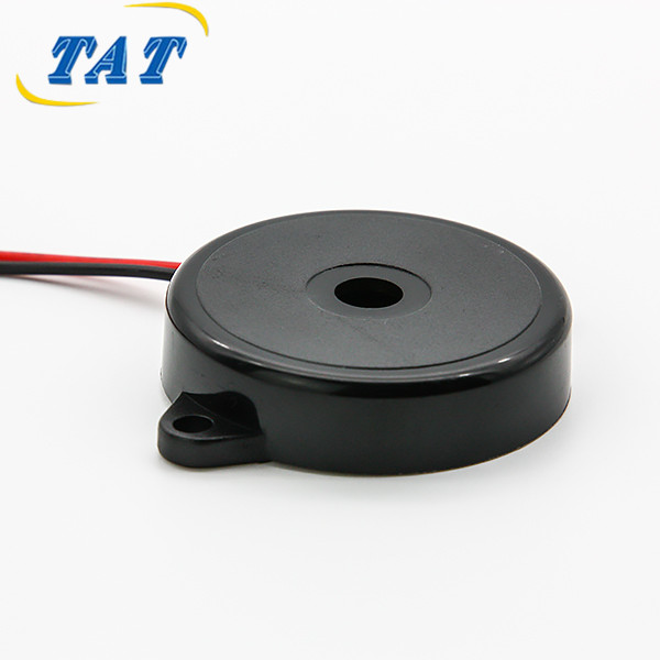
A concrete industrial example makes the geometry clear. The TAT BP3590W100-11 is a passive piezo ceramic sounder, Φ35 × H9.0 mm, operating from 1 to 30 Vp-p with a rated 10 Vp-p square wave. It draws at most 5 mA at 1.1 kHz and 50 percent duty, produces at least 80 dB at 10 cm under the same drive, and resonates at 1100 ± 400 Hz. The housing is black PBT, the pins are tin-plated brass, and the unit leaves the factory with a 100 ± 5 mm lead terminated in an XH2.54-2P connector. Rated operating temperature is -20 to +70 °C, with storage from -30 to +80 °C.
There is no single ESD problem. There are four, and they need different parts because they arrive through different doors.
The XH2.54-2P terminal is metal, it is reachable if the housing leaves it proud of the panel, and it is the first thing a finger or a tool touches. A contact discharge there does not stop at the plastic shell: it enters the conductor and runs the length of the lead into the board. The lead is 100 ± 5 mm of 1.2 mm wire, which is a transmission path, not a protection device. Whatever sits at the far end of it absorbs the event.
The path is underrated because the connector lives on the harness drawing rather than the schematic, so it never appears in the review that assigns protection parts.
Surge is a different animal from ESD: longer duration, far more energy, and it does not need a person. TI's surge diode selection note frames the input TVS as protection against spikes caused by nearby machinery, lightning strikes or power surges, modelled and regulated by IEC 61000-4-5 — a standard written for industrial environments rather than for a technician's fingertip. A 100 mm lead routed beside a contactor coil or a motor cable is an antenna with a return path. The energy arrives common-mode and looks for the lowest-impedance route to ground, often the drive transistor the buzzer sits on.
A 35 mm piezo disc is two electrodes separated by ceramic, which is to say a capacitor with a large area. Put it at the end of a pair of leads and you have built a receiving loop. Fast fields couple into it directly, and the element converts the resulting charge into a voltage across its own terminals. Nothing has to touch the product for this path to work, which is why a unit can pass a contact-discharge check at the connector and still misbehave when the panel it is mounted in is charged.
The last hop is the one that usually fails. The transient that survives the clamp arrives at the base or gate of the drive transistor, couples across it, and reaches the MCU pin on the other side. A GPIO rated for its own supply rail has no margin for a residual pulse, and a pin that latches takes the alarm function with it. This is the path where the choice of clamp matters most, because the clamp's let-through voltage — not its standoff voltage — is what the pin actually sees.
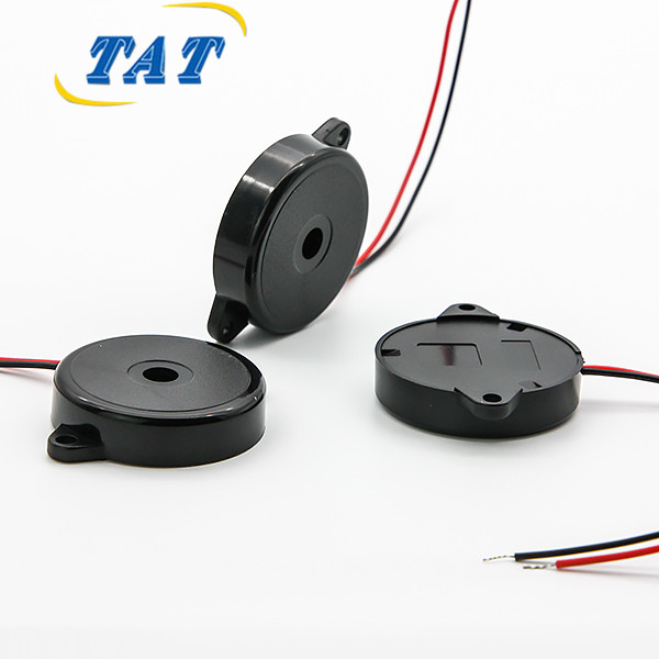
A passive piezo element behaves as a capacitor, and that single fact reorganises the whole protection strategy. There is no DC path through it. At the 1100 Hz drive frequency the element is a reactive load that the drive stage charges and discharges every half cycle, which is why the data sheet specifies a square wave and a current rather than a resistance. At the edge rates of a discharge, the same element is much closer to a short.
The asymmetry is counter-intuitive: the element is often the most robust thing in the circuit, because a capacitor tolerates a fast current pulse far better than a semiconductor does. The energy is not absorbed, only handed on, and it ends at the transistor.
The second consequence is charge retention. With no DC path, whatever charge arrives has nowhere to bleed. A unit that took a hit during handling can sit on the bench with a polarised element, and the first thing the operator hears is a click or a tone that is quieter and harsher than the one that was qualified. A high-value resistor across the element terminals gives that charge a slow path to reference without loading the 1100 Hz drive, and it costs almost nothing.
The third consequence is a limit that is easy to miss. The element is rated over an operating window of 1 to 30 Vp-p. A clamp that lets through more than the peak of that window has moved the part outside its rating, even if the part still makes a sound afterwards. "It still works" is not the same statement as "it is still in specification", and only one of them belongs in a qualification report.
Audio loads punish clumsy protection, because anything you add in parallel or in series changes the signal you were trying to preserve. Four constraints decide the part.
Standoff has to clear normal operation, not the transient. The drive in this example is a symmetric square wave, rated at 10 Vp-p and operable up to 30 Vp-p. A clamp that begins to conduct anywhere inside that window will clip the tone, heat up, and eventually fail short — and it will do so on a bench that never saw an ESD event at all. Choose a bidirectional device whose standoff sits above the largest peak the drive stage can legitimately deliver.
Bidirectional, because the drive is symmetric. A unidirectional clamp conducts on one polarity and behaves like a forward diode on the other, which puts a DC offset across the element and clips half the waveform. The tone changes before anything fails.
Clamp capacitance is not the usual constraint here. In data-line protection the parasitic capacitance of the clamp is the first thing to check, because it distorts fast edges. At 1100 Hz, with an element that is itself capacitive and already the dominant load, a clamp contributing tens to a few hundred picofarads is not the limiting factor. The limiting factor is the inductance of the connection between the clamp and ground.
Series resistance has to go where it costs least. This part draws at most 5 mA at rated voltage, so a series resistor large enough to matter for ESD would also drop the drive and cost sound pressure. Put the resistance between the clamp and the protected pin rather than in the element's own path, where it attenuates the acoustic output.
ESD and surge are two selection exercises, not one. A surge diode is chosen around clamping voltage, standoff and peak pulse capability for a long pulse; an ESD array is chosen for a sub-nanosecond edge. Use one part for both and it usually does neither well: a small ESD array at the pin, a surge-rated TVS at the connector.
TI's ESD protection layout guide states the mechanism plainly: an ESD event forces current into a system, usually through a user interface such as a cable connection, and protection works by shunting that current to ground along a path of the lowest possible impedance. The designer cannot control the injected current, so the only available lever is the impedance of the return path. Three layout consequences follow directly.
The clamp belongs within a few millimetres of the connector, on the same copper, with its ground return going straight into the connector's ground — not into the digital ground plane on the far side of the board. The guide is equally direct about vias: placing one between the discharge source and the TVS is detrimental, because its inductance raises exactly the impedance the clamp exists to lower. And the segment between connector and clamp should be treated as contaminated: no unprotected traces routed alongside it, and no right-angle corners.
Applied to a connectorised sounder, the practical arrangement is a short, wide, direct shunt at the XH2.54 landing area, a ground pour under it tied to the connector ground, the drive transistor behind that clamp rather than beside the connector, and the 100 mm lead dressed away from any switching node. The lead length is fixed by the part, but its route is not.
Formal immunity testing needs a calibrated generator and a reference plane. Screening does not. Four checks catch most of what a lab would later find.
Discharge at the connector, not at the board. Apply the probe to the exposed terminal and to the housing seam, in both polarities, and watch the output on a scope rather than listening to it. A reset, a latched output or a frequency that does not return to 1100 ± 400 Hz is a fail regardless of what the sound suggests.
Measure where the current goes. A current probe around the lead, or a shunt in the ground return, shows whether the clamp is carrying the event or the drive stage is. If the shunt stays quiet during a discharge, the clamp is not in the path.
Re-qualify the acoustics after every event. Compare sound pressure at 10 cm against the pre-test value under the same 10 Vp-p, 1.1 kHz, 50 percent duty drive. Two or three decibels of loss is the signature of a partially damaged element, and it will not be audible to a human ear in a noisy room.
Swap the element to separate the two halves. If a known-good element is silent on the same board, the drive stage is damaged. If it sounds normally, the board is fine and the original element is not.
The symptom usually names the path, if you read it in the right order.
Silent, with the drive pin still toggling. The drive transistor is shorted. This is Path 1 or Path 2, and the fix is a clamp at the connector plus a series element between clamp and pin.
Tone present but several decibels down. The element has been partially depolarised or cracked. This is Path 3, and the response is mechanical and field-related: check mounting torque, check that the aperture is not obstructed, and consider shielding rather than adding more components.
Continuous tone from power-up. The MCU pin is latched or damaged, which is Path 4. Re-examine the clamp's let-through voltage against the pin's absolute maximum rather than its standoff against the supply.
Random chirps during handling with no permanent damage. Charge on an element with no bleed path. A high-value resistor across the terminals is the whole fix.
Fails only on long cable runs in the field, never on the bench. Cable-coupled surge, Path 2. An ESD array will not solve it; the part needs surge-rated clamping and a return path that does not run through the signal ground.
None of these signatures needs a laboratory to observe, only that someone thought about the buzzer before the first customer complaint. If the enclosure itself is the weak point rather than the circuit, the sealing claim is worth checking the same way — the test procedure behind an enclosure rating is a separate investigation with its own vocabulary.
Protection for a sounder is not a component, it is a path. Decide where the energy enters — the connector, the lead, the disc, or the pin — and the parts choose themselves: a surge-rated TVS at the connector, a small ESD array at the pin, a series element between them, a bleed resistor across the element, and a ground return short enough to make all of it meaningful. Get the order wrong and the most expensive clamp on the board will still hand the event to the transistor.
The number worth carrying into every review is not a clamping voltage but a window: 1 to 30 Vp-p on this part, rated at 10 Vp-p. Every decision either keeps the drive inside that window or pushes the element out of specification while it still makes noise.
It protects the element, which is usually the part that needs it least. The vulnerable components are the drive transistor and the MCU pin, and a clamp at the terminals still leaves the lead, the connector and the drive stage exposed. Put the surge device at the connector, where the current enters.
It limits current into the drive stage, which helps, but this part draws at most 5 mA at rated voltage, so any resistor large enough to matter for a discharge also costs sound pressure. Place it between the clamp and the protected pin so the attenuation lands on the logic side rather than on the acoustic output.
No. The element is rated over 1 to 30 Vp-p; a transient that leaves it outside that window can still produce a tone while the level has dropped and the waveform has changed. Re-measure sound pressure at 10 cm under the original drive before signing anything off.
A piezo element is a capacitor with no DC path, so charge delivered during handling has nowhere to bleed. It sits across the element as an offset until the drive signal discharges it. A high-value resistor across the terminals removes the symptom and costs nothing.
Yes, and the standards are separate for that reason: IEC 61000-4-2 describes a sub-nanosecond discharge from a person, while IEC 61000-4-5 describes a much longer, much higher-energy surge from machinery or lightning. An ESD array optimised for the first will not survive the second, and a surge TVS sized for the second is usually too slow and too large for the first.
If you are narrowing candidates for a connectorised sounder, the piezo buzzer range lists the passive and self-drive options with their drive requirements, and our guide to reading the eight lines of a buzzer data sheet explains why the capacitance and drive-signal entries are the two that decide the protection topology. Teams still choosing between drive architectures will find the trade-offs in active versus passive buzzer circuits, and the symptom of a clamp that has eaten too much drive amplitude looks exactly like a piezo that is quiet at 3.3 V.


