
English 
Dedicated to global electroacoustic technology.
Views: 0 Author: Site Editor Publish Time: 2026-11-08 Origin: Site


A piezo buzzer that is too quiet at 3.3 V is almost never a defective part. In most designs the buzzer is fine and the drive condition is wrong: the datasheet sound pressure level was measured at 5 Vp-p or 10 Vp-p, the tone is being generated off the resonant frequency, or an active buzzer rated for 12 V has been dropped onto a 3.3 V rail and barely starts. This guide walks through the symptoms you can observe on a bench, the five root causes behind a piezo buzzer that is too quiet at 3.3 V, and the fixes that recover most of the missing output without changing the enclosure.
The dB number is conditional. A piezo datasheet quotes sound pressure at a specific drive voltage, frequency and duty cycle. Reading the number without the condition is the single most common source of a "quiet" design.
3.3 V logic gives 3.3 Vp-p, not 5 V. Driving a part specified at 5 Vp-p directly from a GPIO removes roughly 3.6 dB before anything else goes wrong.
Resonance is narrow. A passive piezo specified at 4000 ± 400 Hz loses far more output by being driven at 2.7 kHz than by losing a volt of swing.
Active and passive are not interchangeable. An active buzzer with an internal oscillator rated for 12 V will not run from 3.3 V; a passive piezo will run from 3.3 V but only as loudly as that swing allows.
Measure at the datasheet distance and duty cycle. Comparing a 10 cm measurement against a specification taken at 10 cm with a 50% duty square wave is the only comparison that means anything.
Fix the drive, then the acoustics. Amplitude, frequency and the sound opening account for most recoverable output; the transducer itself is usually the last suspect.
"Too quiet" is not a measurement. Before changing parts, separate the three things that get described as quiet: the buzzer is audible but too faint at the target distance, the buzzer is audible only when you lean in, or the buzzer is effectively silent and you are hearing the driver circuit rather than the part.
On a bench, with the buzzer in free air and nothing around it, almost every piezo sounds loud. In the product it sits behind a wall, under a label or inside a sealed housing, and the same part reads as quiet. If the bench unit is loud and the assembled unit is not, the problem is in the acoustic path, not in the drive electronics. Reversing that order — swapping buzzers first — is how a simple aperture problem turns into three rounds of samples.
A useful first test takes two minutes: hold the assembled unit next to the bare buzzer, drive both from the same signal, and listen at the same distance. If the bare part is clearly louder, stop looking at the buzzer specification.
Datasheet sound pressure values for these parts are quoted at 10 cm. That distance is short enough to measure reasonably in a normal room, provided you do three things: keep the meter directly on axis, keep the room quiet enough that the buzzer is at least 15 dB above the ambient floor, and use the same drive conditions the datasheet used. A 50% duty square wave at the resonant frequency is the standard condition in the TAT specifications below.
Table 1: Triage table — symptom to first check
What you observe | Most likely cause | First check |
|---|---|---|
Bare buzzer loud, assembled unit faint | Acoustic path blocked or short-circuited | Sound opening size, sealing, potting over the aperture |
Faint at every frequency | Drive amplitude below the specified condition | Actual Vp-p across the buzzer with a scope |
Loud at one tone, faint at the target tone | Driven off resonance | Generated frequency versus datasheet resonant frequency |
Silent, with a click at power-up | Active buzzer rated above the rail | Part type and rated voltage |
Faint and distorted at high drive | Drive stage clipping or saturating | Driver supply headroom and series resistance |
Output falls as volume rises in software | PWM carrier or duty handling | Duty cycle at the pin, not in the timer register |
This is the most common cause, and the most invisible, because the datasheet is not wrong — it is conditional. The three passive piezo models below quote their sound pressure at 5 Vp-p or 10 Vp-p, which is well above what a 3.3 V GPIO can produce.
Table 2: Drive conditions as specified for three passive piezo models
Model | Type | Operating voltage | Resonant frequency | Sound pressure | Capacitance |
|---|---|---|---|---|---|
BP1360C-40-P5.0/7.6 | Passive piezo, external drive | 1 – 25 Vp-p | 4000 ± 400 Hz | ≥ 80 dB at 10 cm, 4 kHz 50% duty, 5 Vp-p | 11000 ± 30% pF at 120 Hz |
BP1770C-0540 | Passive piezo, external drive | 1 – 30 Vp-p | 4000 Hz (square wave drive) | ≥ 85 dB at 10 cm, 5 Vp-p | 15000 ± 30% pF at 120 Hz, 1 V |
BP1032W18-48 | Passive piezo | 1 – 30 Vp-p | 4800 ± 500 Hz | min. 75 dB at 10 cm, 4.8 kHz 50% duty, 10 Vp-p | 8000 ± 30% pF at 1 kHz |
Read the last column pair together: the same family of parts is specified at 5 Vp-p and at 10 Vp-p depending on the model. A 3.3 V rail cannot reach either condition on its own.
For a piezo element, radiated pressure rises with the drive voltage, so a reduction in swing shows up directly as a reduction in level. Using the logarithmic relationship as an illustrative method only:
Table 3: Illustrative level change versus drive voltage (method example, not a specification)
Specified at | Driven at | Calculated change |
|---|---|---|
5 Vp-p | 3.3 Vp-p | about −3.6 dB |
5 Vp-p | 3.3 Vp-p, single-ended from a GPIO with 0.4 V drop | about −5 dB |
10 Vp-p | 3.3 Vp-p | about −9.6 dB |
Illustrative method only; not a product specification. Change ≈ 20 × log₁₀(V₂ / V₁).
A 3.6 dB loss is audible but usually not fatal. A 9.6 dB loss is the difference between a part that meets its application and one that reads as quiet. That is why the BP1032W18-48, specified at 10 Vp-p, feels dramatically weaker on a 3.3 V rail than the BP1360C does — even though both are 1–30 Vp-p capable parts.
A passive piezo is a resonant device, not a wideband speaker. Its output peaks sharply near the specified resonant frequency and falls away quickly on either side. Driving a 4000 ± 400 Hz part at 2.7 kHz because that frequency was convenient in a timer register costs far more output than a volt of swing ever will.
The same trap appears in the opposite direction: a designer picks a 4800 Hz part for a 4 kHz alert tone, then wonders why the tone is weak. Either move the tone to the part's resonant frequency, or pick a part whose resonant frequency matches the tone the product needs. Do not split the difference.
There is a second-order effect worth knowing. Off resonance the element looks more capacitive and less resistive, so the current drawn for a given voltage can rise while the acoustic output falls. A part that draws more current and sounds quieter is a strong signal that the drive frequency is wrong.
An active buzzer contains its own oscillator. It needs a DC supply within its rated range and produces a fixed tone. Put a 12 V active part on a 3.3 V rail and it either stays silent or emits a faint click as the internal circuit tries to start.
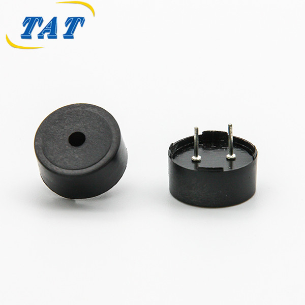
This is a selection error, not a tuning error, and it is easy to make because active and passive parts share body sizes and mounting styles. In the piezo range, active models such as the BPC2310 (23 mm, 12 V, continuous tone, internal drive) and the BPC3215W100-1235 (32 × 15 mm, 12 VDC, 3500 Hz) are built around a nominal 12 V supply. The BPC3025W150-1235 is specified across 5–24 VDC, which still leaves 3.3 V outside its range.
The check is one line in the datasheet: does it say external drive or internal drive? External drive means you supply the waveform. Internal drive means you supply a DC voltage inside the rated window.
A GPIO pin driving a piezo directly has two limits: the pin's output high voltage under load, and its current capability. Piezo elements are capacitive, so the load is reactive — at 4 kHz a 11000 pF element presents roughly 3.6 kΩ of reactance, which draws under a milliamp at 3.3 V. Current is therefore rarely the problem. The problem is that anything in series with the element — a 100 Ω resistor added "for safety", a long thin trace, a connector, an electrolytic in the wrong place — forms a divider with that reactance and removes swing where it matters.
Worse, some designs drive the piezo through an emitter follower or a level shifter that was chosen for a logic signal rather than for a 3.3 V swing into a capacitive load. The stage looks correct on a schematic and delivers 2.4 Vp-p at the part.
A piezo element radiates from both faces in opposite phase. Mount it in an open frame with both faces exposed to the same air volume and the two pressure waves cancel at low frequencies — the classic acoustic short circuit. The result is a part that measures well on the bench and sounds hollow and weak once installed.
Three installation habits cause most of it: an aperture that is too small relative to the element diameter, a gasket that seals the front but leaves the back open to the same cavity, and potting compound flowed over the sound opening. In each case the electronics are delivering exactly the swing they were designed to deliver, and the product is still quiet.
Start by writing the actual numbers down: rail voltage, the Vp-p the drive stage can deliver into a capacitive load, the datasheet Vp-p condition, and the datasheet sound pressure at that condition. If the first two are smaller than the third, you have found the gap without touching hardware.
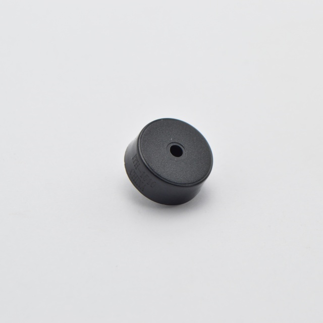
If the part is active and its rated voltage is 12 V, no amount of tuning will make it work at 3.3 V. Replace it with a passive piezo — the piezo buzzer range is organised by drive type, so this is a catalogue decision rather than a redesign — or move to a magnetic transducer whose rated voltage matches the rail, which is a different trade-off on current and tone quality. Where board space allows a 17 mm body, the BP1770C-0540 shows the same 1–30 Vp-p external-drive arrangement in a pin-mount package.
Set the tone generator to the part's resonant frequency and verify it at the pin with a scope, not in the timer configuration. A prescaler rounding error of a few percent is enough to sit visibly off the peak on a narrow resonance.
For a 4000 ± 400 Hz part, generate 4000 Hz. For a 4800 ± 500 Hz part, generate 4800 Hz. If the product's alert tone must be a different pitch, choose the part by its resonant frequency instead of forcing the tone — this is exactly the decision that separates the BP1360C-40-P5.0/7.6 from the BP1032W18-48.
Also confirm the duty cycle. The specified conditions above use a 50% duty square wave. A 10% duty pulse train contains the fundamental, but at a much lower amplitude, and it is a frequent accidental cause of "it got quiet after the firmware change".
Once frequency is correct, amplitude is the only lever left on the electronics side, and there are two clean ways to get it.
The first is a push-pull or bridge stage. Driving a piezo differentially swings it from −V to +V instead of 0 to +V, which doubles the peak-to-peak voltage for the same supply. In the illustrative terms of Table 3, doubling the swing is worth about 6 dB — more than recovering the 3.6 dB lost between 5 Vp-p and 3.3 Vp-p.
The second is a higher rail for the buzzer alone. A small boost converter or an existing 5 V or 12 V rail feeding a single switching device lets a 3.3 V logic system drive the element at its specified condition. This is often the cheapest fix in a product that already has a 5 V rail for other reasons, and it keeps the logic side untouched.
What does not work is adding series resistance to "protect" the pin. The pin is driving a reactance, not a short, and the resistor removes exactly the swing you are trying to preserve.
With the electronics delivering the specified Vp-p at the specified frequency, the remaining variable is the path out of the enclosure. Three checks resolve most cases: the sound opening should be at least comparable to the element diameter, the front and back of the element should not share one sealed cavity, and no coating or potting should cover the aperture.
If the design needs a sealed front chamber, add a defined leakage path behind the element rather than sealing both faces. If the buzzer is gasketed to a wall, verify the gasket seals around the aperture rather than across it.
Fix the test before fixing the part. The workable routine is short: drive the buzzer at its resonant frequency with a 50% duty square wave at the intended Vp-p, place the meter 10 cm on axis, and record both the number and the drive conditions. Repeat it after every change.
Table 4: Passive versus active at 3.3 V — selection table
Requirement | Passive piezo | Active piezo | Note |
|---|---|---|---|
Runs from 3.3 V logic directly | Yes, with reduced level | Only if rated for 3.3 V | Check rated voltage window first |
Tone can be changed in firmware | Yes | No, fixed tone | Passive needs a square wave source |
Loudest output for a given swing | At resonance | At its fixed frequency | Off-resonance drive wastes both |
Typical drive condition on these parts | 1–30 Vp-p, external drive | 5–24 VDC or 12 VDC nominal | Compare like for like |
A purchase specification that says "≥ 80 dB at 10 cm" is not a specification — it is a fragment. Add the voltage, the duty cycle, the frequency and the distance, and require the supplier to state all four. When the condition is written down, the 3.3 V argument happens at the drawing stage instead of at the first prototype review.
The same discipline applies to the driver. Write the required Vp-p at the buzzer terminals into the schematic notes, not just the rail voltage, so that whoever adds a series component later can see what it will cost.
Output at 10 cm under a fixed drive condition is a fast, cheap incoming check that catches both wrong-type deliveries and weak batches. Two conditions are enough: measure a known-good reference unit at the start of each session, and measure every incoming lot against it at the same distance and drive. Anything that sits more than a few dB low is worth a conversation with the supplier before it reaches a production line.
Keep the reference unit and its measurement record. Without a baseline, every future "this one sounds quieter" complaint restarts the same investigation.
A piezo buzzer that is quiet at 3.3 V is usually doing exactly what it was told to do. The datasheet level was measured at 5 Vp-p or 10 Vp-p, the element is being driven off its resonant frequency, or an active part rated for 12 V has been asked to start on a 3.3 V rail. None of those are transducer faults.
The fix sequence is deliberately boring: confirm the type, rebuild the voltage budget, generate the resonant frequency, recover swing with a bridge or a suitable rail, then check the acoustic opening. In practice the first two steps resolve most cases before any hardware changes.
Before the next build, write the drive condition into the specification and put a 10 cm SPL check on incoming inspection. Review the passive options in the piezo buzzer range, compare against magnetic buzzers if the rail is fixed and low, and check SMD buzzers if the assembly is reflow-only. If the tone still does not fit the application after that, send the target conditions through the contact page and specify them numerically rather than by description.
A: Because the datasheet number carries a drive condition. The TAT passive piezo models are specified at 5 Vp-p or 10 Vp-p with a 50% duty square wave at their resonant frequency. A 3.3 V rail delivers 3.3 Vp-p, which is below that condition, so the sound pressure is lower by definition rather than by defect.
A: Yes for a passive element, and current is rarely the limit — a 11000 pF element at 4 kHz presents roughly 3.6 kΩ of reactance. The limitation is amplitude: the pin can only swing the rail, so the buzzer sees 3.3 Vp-p at best. If the application needs the datasheet level, the element must be driven from a stage that provides the specified Vp-p.
A: The acoustic path, in most cases. A piezo element radiates from both faces in opposite phase, so mounting it with both faces open to the same cavity cancels the low end. Small apertures, a gasket sealing across the opening, or potting over the sound hole produce the same result. Test the bare part and the assembled unit side by side at the same distance before changing the transducer.
A: Read the drive description. Passive parts are listed as external drive and need a square wave at their resonant frequency; active parts contain an oscillator, are listed as internal drive, and need a DC supply inside their rated voltage window. In the TAT piezo range that distinction is stated in the specification table for each model, and it determines whether 3.3 V will run the part at all.
A: Correct the frequency first, then the amplitude. Driving at the specified resonant frequency costs nothing and recovers the largest single loss in most designs. After that, a bridge or push-pull stage doubles the swing, worth roughly 6 dB in the illustrative terms used above. Check the sound opening last, once the electrical side is known to be delivering the specified Vp-p.


