
English 
Dedicated to global electroacoustic technology.
Views: 0 Author: Site Editor Publish Time: 2026-11-18 Origin: Site


Wearable audio designs keep getting thinner, and the microphone is often the part that decides whether the housing can close. A 4015-size electret condenser microphone gives you a Φ4.0 x 1.5 mm capsule that weighs no more than 0.2 g, runs from a standard 2 V supply and draws at most 0.5 mA — but the electrical figures are only half the decision. The other half is how the capsule physically connects to your product.
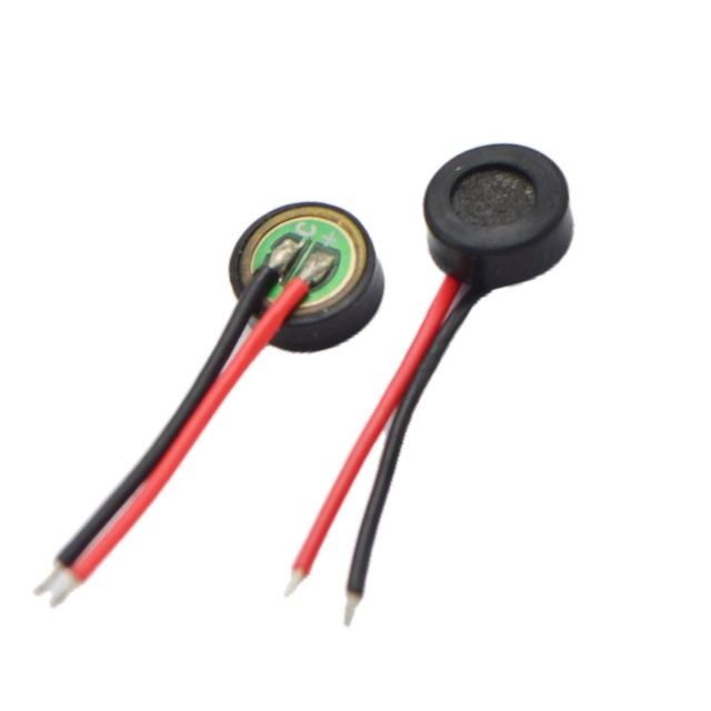
The TAT-EM4015 is available in four termination variants: SMD pads, pin holes, through-hole pins and pre-attached wire leads. Each one fits a different assembly flow and a different mechanical constraint. This article walks through all four, then covers how the three selectable sensitivity grades map onto real preamplifier designs.
The M4015A puts flat solder pads on the base of the capsule instead of pins or wires. That single change moves the part onto your pick-and-place line: the microphone is placed like any other SMD component and reflowed with the rest of the board, so there is no separate hand-soldering step and no wire routing to design around.
Two practical notes. First, the flat base preserves the low profile of the capsule, which matters when the acoustic port sits close to the PCB. Second, reflow heat is the constraint — the internal electret material has a thermal limit, so the oven profile has to be checked against the part rather than copied from a neighbouring component. Where the profile fits, this is the variant that scales best into TWS earbuds, fitness bands and other slim Bluetooth headsets.
When reflow is impractical, the M4015B exposes pin holes on the base. You can solder flying wires into them, which keeps heat local and lets you position the capsule wherever the acoustic port actually is — on a stalk, behind a mesh, or away from the main board entirely.
That off-board freedom is the reason this variant shows up in prototypes and in voice-assistant products where the microphone has to sit near the user rather than near the power stage. The trade-off is repeatability: hand-soldered joints depend on the operator, so dwell time and strain relief on the wires need to be written into the work instruction. Output impedance stays below 2.2 kΩ, which keeps longer wire runs from degrading the signal as much as they otherwise would.
The M4015P extends straight pins from the base for wave soldering or socket mounting on double-sided boards. Mechanically, pins that pass through the PCB anchor the capsule far more securely than surface adhesion — useful in automotive hands-free units, dash cams and other in-car electronics that see continuous vibration.
Electrically, this variant is also the one to reach for when the supply is not clean. The capsule's sensitivity reduction is specified as within 3 dB at 1.5 V, so a rail that sags from the standard 2 V still leaves usable output. Socket mounting is worth considering as well: if a microphone may need replacement in the field, a socket avoids desoldering the board.
| Mounting method | Termination | Typical assembly | Good fit for |
|---|---|---|---|
| M4015A | SMD pads | Pick-and-place plus reflow | TWS earbuds, wearables |
| M4015B | Pin holes | Hand soldering, flying wires | Prototypes, off-board mics |
| M4015P | Through-hole pins | Wave solder or socket | Automotive, dash cams |
| Wire-lead | Red and black leads | Pre-attached, hand connect | Sealed or remote capsules |
The fourth variant leaves the factory with red and black leads already attached. It is the version the product page lists as the waterproof option, and it exists for the case where the capsule cannot sit on the main board at all — a sealed earbud stem, a sweat-exposed sports band, or a housing where the acoustic path and the electronics are in different compartments.
Because the leads are pre-attached, assembly becomes a wiring task rather than a soldering task on the capsule itself. Two things still need attention. The lead entry point into the housing is where moisture protection is won or lost, so it needs a gasket or sealing step designed for it. And the leads should not carry mechanical load — strain relief belongs on the housing, not on the solder joint.
All four variants share the same three sensitivity options, measured at 1 kHz with 0 dB referenced to 1 V/Pa: -46 ±3 dB, -44 ±3 dB or -42 ±3 dB. All three keep a signal-to-noise ratio above 56 dB.
The choice is mostly about headroom. A capsule sitting close to the mouth — an earbud stem mic or a boom mic — produces a strong signal, so the -46 dB grade gives the preamplifier room before clipping. A capsule placed further away, in a smart speaker or a voice assistant, benefits from the higher output of the -42 dB grade so that later digital gain stages do not have to amplify noise along with the voice. The correct answer depends on the acoustic distance and the gain structure behind the microphone, not on which grade looks better on paper.
For background on how electroacoustic measurements are standardised, IEC 61672-1:2013 covers sound level meter characteristics and is worth reading in its current edition rather than a superseded one. If you need the metrology side rather than the instrument side, the NIST Physical Measurement Laboratory publishes the underlying measurement background.
Termination is an assembly decision, and it is worth making it before the housing is drawn. SMD pads buy automation and a flat profile; pin holes buy placement freedom; through-hole pins buy mechanical anchoring; wire leads buy a sealed, remote capsule. All four keep the same core capsule: Φ4.0 x 1.5 mm, at most 0.2 g, 2 V operation, 0.5 mA maximum current draw and a signal-to-noise ratio above 56 dB. You can compare the full range on the electret microphone category page, or look at the TAT-EM4015 product page for the complete specification table.
If you need a larger capsule for the same design, the EM6050P 6.0 x 5.0 mm electret condenser microphone uses the same pin-mount logic, and the M4520W high-sensitivity ECM is the wire-lead option when a slightly larger body still fits the enclosure.
The microphone needs a supply and a load. A 2 V rail feeds the capsule through a bias resistor sized for the current the preamplifier expects, and a coupling capacitor takes the audio off the capsule without passing DC to the codec or amplifier. The exact resistor value belongs to your preamplifier design; what the datasheet fixes is the 2 V standard operating voltage and the 0.5 mA maximum current consumption, which together bound the resistor choice.
Sensitivity reduction is specified as within 3 dB at 1.5 V. In practice a rail that falls from 2 V to 1.5 V costs you a small amount of output rather than a step change, so a device with a weakening battery keeps capturing voice.
Go higher. The -42 ±3 dB grade gives more output at the same sound pressure, which keeps the signal above the noise floor of the following stage when the acoustic distance is large. Reserve -46 ±3 dB for close-talk positions where clipping is the bigger risk.
No. Current consumption, impedance, signal-to-noise ratio and sensitivity options are the same across the four termination variants. What changes is the mechanical interface: the wire-lead version is the one supplied as the waterproof option, and it needs a sealed entry point and strain relief in the housing design.
Not without a layout change. The SMD pad variant needs a reflow footprint, the pin hole and through-hole variants need drilled holes, and the wire-lead variant needs a cable route and a strain relief point. It is cheaper to fix the termination choice before the mechanical drawing is released than to re-spin the board afterwards.


