
English 
Dedicated to global electroacoustic technology.
Views: 0 Author: Site Editor Publish Time: 2026-11-22 Origin: Site


A self-drive magnetic buzzer looks like the simplest part on the board: one leg to a supply, one leg to ground, and it makes a noise. The BMC9650 is exactly that kind of part, and that is also where most of the design mistakes happen. Designers size the drive as if they were driving a resistive load, then wonder why the tone drifts, why the volume falls short at the low end of the supply, or why a GPIO pin runs warm.
The coil inside an electromagnetic buzzer is not a resistor. It is an inductor with a DC resistance, and it wants very specific things from whatever is switching it. The BMC9650 answers part of that demand itself, because the oscillator sits inside the housing. What is left for your circuit is smaller, but it still has to be right.
An external-drive buzzer is close to a tiny loudspeaker. There is no oscillator inside, so the board has to supply the AC signal: a transistor pair, an RC network, or a PWM channel from the microcontroller, configured at the right frequency and duty cycle. Change the frequency and the pitch changes with it.
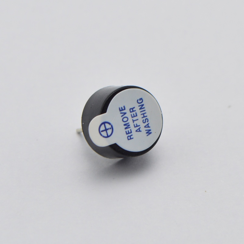
A self-drive part such as the BMC9650 carries its own oscillator. Apply a DC voltage across the terminals and the internal circuit starts switching the coil, which pulls the diaphragm and produces a steady tone. Nothing on your board has to generate a waveform, and nothing in your firmware has to hold a timer.
| Feature | Self-Drive Buzzer (BMC9650) | External-Drive Buzzer |
|---|---|---|
| Input signal | Plain DC voltage | AC signal or PWM |
| Board components | None beyond the switch | Oscillator or PWM source |
| Firmware | GPIO high or low | Timer and PWM configuration |
| Tone | One fixed frequency band | Any frequency the drive can produce |
That trade is the whole point of the part. You give up the ability to play melodies, and in exchange the alert logic collapses to a single pin. For a door entry unit, a washing machine panel or a panel-mount alarm, that is usually the right trade.
Even with the oscillator inside, three things still sit on your side of the terminals: the rail, the switch, and the return path. The published numbers for this part describe what the coil will do when those three are right.
| Feature / Specification | Target Value | What It Means for the Drive |
|---|---|---|
| Operating Voltage | 1.5 V to 12 V DC | Direct connection to a standard rail, no regulator |
| Current Consumption | 20 mA to 50 mA | A small transistor or a strong GPIO pin can carry it |
| Sound Pressure Level | 85 dB to 95 dB at 10 cm | Audible alert without a horn or cavity |
| Operating Frequency | 2 kHz to 4 kHz, ±2% to 3% | A band the ear is most sensitive to, held tight |
| Mounting | SMD / Through-hole (DIP) | Fits reflow or wave soldering lines |
The first thing the coil asks for is a steady rail. Because the oscillation is generated inside the housing, the only external stimulus the part needs is a DC level. That removes the external oscillator, the timing components around it, and the firmware that would otherwise keep a PWM channel busy.
In practice this is where BOM cost quietly drops. One transistor, one resistor and one decoupling capacitor can replace a small forest of parts, and the board area that would have held them goes back to routing. It also removes a class of failure that is hard to debug in the field: a drive frequency that drifts with temperature because the RC network around it drifts.
The second demand is current. This part draws between 20 mA and 50 mA while it is sounding, which is modest but not nothing. A GPIO pin on a small microcontroller can usually sink that, but the pin also has to survive the inductive kick when the internal switch turns the coil off.
The safe pattern is a small NPN or MOSFET between the buzzer and ground, with the GPIO driving the gate through a resistor, and a flyback path across the coil. That keeps the pin current in the microamp range and puts the switching stress where it belongs. Check the transistor's saturation voltage as well: a part that drops a volt in saturation takes that volt away from the coil and costs you output.
The third demand is the supply window. The published operating range is 1.5 V to 12 V DC, which covers everything from a pair of alkaline cells to a 12 V industrial rail. The part will run across that whole span, but it will not sound identical at both ends.
Sound pressure tracks the supply, so a design that is specified at 12 V and then powered from a 3 V rail should be checked against the 85 dB to 95 dB figure at that rail rather than assumed. If the alert has to stay above a fixed loudness threshold, either fix the rail with a regulator or verify the level at the worst-case voltage your product will actually see.
The tone itself sits between 2 kHz and 4 kHz with a tolerance of plus or minus 2 to 3 percent. The band is deliberate: human hearing is most sensitive in that region, which is why a 9.6 mm class part can still cut through machinery noise.
The tolerance is a batch property, not a supply property, but the supply can still move the perceived pitch if the rail is noisy. A switching regulator with visible ripple on the same rail will modulate the coil current, and the result is a tone that sounds rough even though the part is within specification. Decouple locally, and keep the buzzer's return path away from the switching node.
Finally, the coil assembly needs to survive your assembly process. The part is offered in both surface-mount and through-hole formats, so the same electrical design can be built on a reflow line or a wave solder line without a board redesign.
The SMD version suits dense boards that go through reflow. The through-hole version gives a stronger mechanical anchor, which matters on panels that see vibration or on boards that are routinely handled during service. Choose it at the layout stage, not after the stencil is cut.
The combination of an internal oscillator, a 1.5 V to 12 V range and a small round housing puts this part in three recurring situations:
If the requirement is a smaller body, the BMC1295 magnetic buzzer covers a similar self-drive role in a different can size. Where a wider panel opening allows a larger resonator, the BMC1614 magnetic buzzer is the same construction scaled up. For pin-mount assemblies, the BMC1370S magnetic buzzer is the through-hole option worth comparing before you commit to a footprint.
The internal oscillator is also a limit. Because the frequency is fixed inside the housing, this part cannot produce melodies, two-tone patterns or voice. If the product needs a chime, a siren sweep or an audio prompt, the design needs an external-drive buzzer or a small speaker and a codec, and no amount of drive circuitry on your side will change that.
The second limit is thermal. The coil dissipates while it sounds, so a duty cycle that keeps the buzzer on continuously for minutes is a different thermal case from a two-second alert. If the application holds the tone for long periods, check the coil temperature rather than assuming the electrical ratings cover it.
The third limit is mechanical. The diaphragm needs clear space in front of it. A gasket that presses on the diaphragm, or a housing wall that sits flush against the sound port, will mute the part and make a good design look like a bad component. If the panel needs a larger aperture and a louder part, the BM1290 electromagnetic buzzer is the external-drive comparison to run before changing the mechanical drawing.
The coil inside a self-drive magnetic buzzer is an inductor, and an inductor wants three things: a rail it can trust, a switch that can carry 20 to 50 mA without stealing voltage, and a return path that is not shared with a switching node. The BMC9650 removes the oscillator from that list by putting it inside the housing, and publishes a 1.5 V to 12 V DC range, an 85 dB to 95 dB output at 10 cm and a 2 kHz to 4 kHz tone held to plus or minus 2 to 3 percent.
Get those three things right and the part behaves the way the published figures say it will. Get them wrong and no amount of firmware tweaking will fix the tone.
It draws 20 to 50 mA, which is inside the absolute maximum of many microcontroller pins but close enough to the edge that a small transistor is the better choice. A GPIO-driven NPN or MOSFET also gives you a place to put the flyback path, which protects the pin from the inductive kick when the internal switch releases the coil.
No. The oscillator is inside the housing and runs at a fixed frequency between 2 kHz and 4 kHz, within plus or minus 2 to 3 percent. To change pitch you have to change parts: an external-drive buzzer or a small speaker driven by a PWM channel is the route for melodies and multi-tone patterns.
Sound pressure follows the supply. The part operates from 1.5 V to 12 V DC, and the published 85 dB to 95 dB figure is measured at 10 cm, so a design that runs near the bottom of the range should be verified at that voltage rather than at 12 V. If the alert must stay above a fixed threshold, regulate the rail or test at the worst case.
That is usually the rail, not the buzzer. Ripple from a switching regulator modulates the coil current, and the resulting amplitude and frequency modulation is audible as roughness. Decoupling the buzzer locally and keeping its ground return away from the switching node normally clears it up.
Choose by assembly and by mechanical load, not by price. The SMD version suits dense reflow boards; the through-hole version anchors better where the panel vibrates or the board is handled during service. Both are the same electrical part, so the decision belongs at layout time.


