
English 
Dedicated to global electroacoustic technology.
Views: 0 Author: Site Editor Publish Time: 2026-10-22 Origin: Site


A piezoelectric buzzer and a magnetic buzzer differ in seven measurable ways, and they all trace back to one structural fact: the piezo part has no moving coil, and the magnetic part has no ceramic element. That single difference sets the voltage window, the current draw, the drive circuit topology, the resonant band, the wear mechanism and the EMI footprint. In practice it also sets the cost of getting it wrong — a magnetic buzzer driven straight from a microcontroller pin will damage the pin, and a piezo buzzer chosen for a 1.5 V rail will not produce usable output at all. This guide works through all seven differences with the numbers behind each one, using parts from TAT's own catalogue as reference points.
The mechanism is the whole story: A piezo buzzer bends a ceramic disc bonded to a metal plate. A magnetic buzzer pulls and releases a ferromagnetic diaphragm with a coil. Everything else in this comparison follows from that.
Only one of them has a wear mechanism: The piezo element is solid state with no rubbing or striking surfaces. A magnetic buzzer moves its diaphragm on every cycle, so diaphragm fatigue and coil degradation are real long-term failure modes.
The voltage windows barely overlap at the bottom: A magnetic buzzer runs at 1.5–12 V DC. A piezo element typically accepts 1–25 Vp-p and above, which suits 12 V and 24 V rails but is a poor match for a 1.8 V logic supply.
Current draw differs by roughly an order of magnitude: A representative passive piezo draws a maximum of 3 mA. A representative magnetic buzzer draws up to 30 mA. For a battery-powered product that difference decides the power budget.
The load types are opposite, so the drivers are opposite: Piezo elements are capacitive and need a stage that both sources and sinks charge. Magnetic buzzers are inductive and need a transistor plus a flyback diode.
Magnetic runs lower and warmer, piezo runs higher and sharper: Typical magnetic resonance sits at 1–3 kHz; typical piezo resonance sits at 2.5–4 kHz, close to the peak of human hearing sensitivity.
The EMI difference is structural, not a design detail: A coil radiates a magnetic field. A ceramic disc does not. That is why piezo parts can sit beside radio modules and precision sensors without shielding.

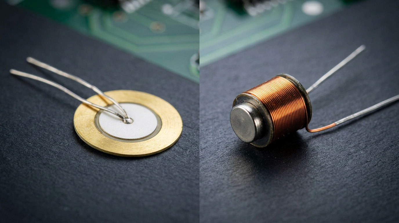
Table 1: The Seven Differences at a Glance
# | Difference | Piezoelectric buzzer | Electromagnetic (magnetic) buzzer |
|---|---|---|---|
1 | Mechanism | Ceramic disc deforms under voltage | Coil pulls a ferromagnetic diaphragm |
2 | Moving parts | None | Diaphragm on every cycle |
3 | Operating voltage | Wide, typically 1–25 Vp-p and above | Narrow and low, typically 1.5–12 V DC |
4 | Current draw | A few mA or less | Tens of mA |
5 | Load type | Capacitive | Inductive, low DC resistance |
6 | Resonant band | 2.5–4 kHz | 1–3 kHz |
7 | EMI | Negligible | Local magnetic field |
A piezoelectric element works by the inverse piezoelectric effect. The ceramic is poled during manufacture so that an applied electric field produces a strain; because the disc is bonded to a brass or stainless steel plate, the strain becomes bending. Apply an alternating voltage and the plate flexes at the drive frequency, pushing air. Nothing in that chain moves in the mechanical sense — the displacement is microscopic and comes from the crystal structure changing shape.
An electromagnetic buzzer works by magnetic attraction. Current through a coil produces a field that pulls a ferromagnetic diaphragm towards a pole piece; reverse the current or interrupt it and the diaphragm springs back. The diaphragm travels on every cycle, and the acoustic output is a direct consequence of that travel.
The practical consequence is that these are not two grades of the same product. They are two different transducers that happen to solve the same problem, and their specifications are not interchangeable.
A piezo element has no wear surface. There is no contact that rubs, no diaphragm that strikes a pole piece, and no bearing or suspension that fatigues. The displacement is elastic deformation of the ceramic and its substrate, and it repeats without accumulation.
A magnetic buzzer does have a wear mechanism, and it is inherent to the design. The diaphragm flexes towards and away from the pole piece on every cycle, so at 2700 Hz it completes more than 230 million cycles in a day of continuous operation. Over a long service life the suspension can fatigue, the diaphragm can develop a permanent set, and the coil insulation is subject to thermal cycling. These are not defects — they are the normal aging path of a moving-diaphragm device, and a well-built part is designed around them.
For most applications this difference does not decide the choice. A door alarm that sounds for a few seconds at a time will never approach the fatigue limit of a decent magnetic buzzer. It matters in continuous-duty signalling — a machine running an alert tone for hours, a status indicator that beeps perpetually — where the piezo element's absence of a wear mechanism is a genuine reliability advantage rather than a datasheet talking point.
This is where the two technologies diverge most sharply, and where mismatches are most expensive.
Electromagnetic buzzers operate at low DC voltages, typically 1.5–12 V. That is a direct fit for 3.3 V and 5 V logic rails, for automotive accessory supplies, and for single-cell battery products. The coil needs enough current to develop the field, but it does not need a high voltage to do it.
Piezoelectric elements are the opposite: they need voltage, not current. A passive piezo in TAT's range such as the BP1770-40 passive piezo ceramic buzzer accepts 1–25 Vp-p, and its output is specified at a 5 Vp-p square wave. Active piezo models go higher still — the BPC2316-2431 is rated 24 V DC with a 5–28 Vp-p operating window.
Two rules follow. First, a piezo part quoted at 24 V will not deliver its catalogue sound pressure level on a 12 V rail; the shortfall is larger than most engineers expect, because output scales roughly with drive voltage. Second, a piezo element on a 1.8 V rail is close to unusable regardless of how you drive it, which rules out the technology for the lowest-voltage logic designs unless you add a boost stage.
For a full view of the voltage and size combinations available, the piezo buzzer range covers formats from 9 mm through 43 mm.
The current difference is roughly an order of magnitude, and it is the reason piezo buzzers dominate battery-powered designs.
A passive piezo is a capacitor. It draws charging and discharging current as the element flexes, but no continuous DC current, and the resulting average draw is small. The BP1770-40 is specified at a maximum of 3 mA — and note the conditions: at 4 kHz, 50 % duty cycle, driven at 5 Vp-p. Change the drive conditions and the current changes with them.
A magnetic buzzer draws coil current continuously while it is sounding. A representative active part in a 9.2 × 5.5 mm body is specified at a maximum of 30 mA. That is ten times the piezo figure, sustained for as long as the alarm is on.
The right way to use these numbers is to compute the average draw over the alarm's duty cycle. An alarm that sounds for two seconds every hour costs almost nothing either way. An alarm that sounds continuously, or a status tone that beeps on every user interaction, is where the 3 mA versus 30 mA gap becomes a battery-life argument.

The two technologies present opposite electrical loads, so they require opposite drive circuits. Getting this wrong is the most common cause of damage in this category.
A passive piezo is a capacitor of roughly 10–20 nF — the BP1770-40 is specified at 15 000 pF ± 30 % at 1 kHz — so it blocks DC, passes no steady current, and has to be both charged and discharged by the driver. A magnetic buzzer is an inductive coil of a few tens of ohms, so it passes DC, looks resistive to a multimeter, and stores energy in its field that has to go somewhere when the switch opens.
A passive piezo needs to be charged and discharged, so the driver must be able to both source and sink. A single-ended switch with a pull resistor will produce sound, but at reduced output and with an asymmetric waveform. A push-pull pair or a bridge is the correct topology, and it also lets you drive the element at its resonant frequency efficiently.
A magnetic buzzer needs a switch that can carry the coil current, plus a path for the coil's energy when the switch opens. Without a flyback diode across the coil, the collapsing field produces a voltage spike that will eventually destroy the driver transistor and can reach the microcontroller through the gate or base network. The transistor is not optional either: tens of milliamps exceeds what most GPIO pins are specified to source continuously.
A useful diagnostic, incidentally: if a passive piezo produces nothing at all, the drive signal is the first thing to check, because a piezo element driven at DC is silent by construction. If a magnetic buzzer produces a click but no tone, the drive frequency is the first thing to check, because the coil responds to any current but only resonates in its designed band.
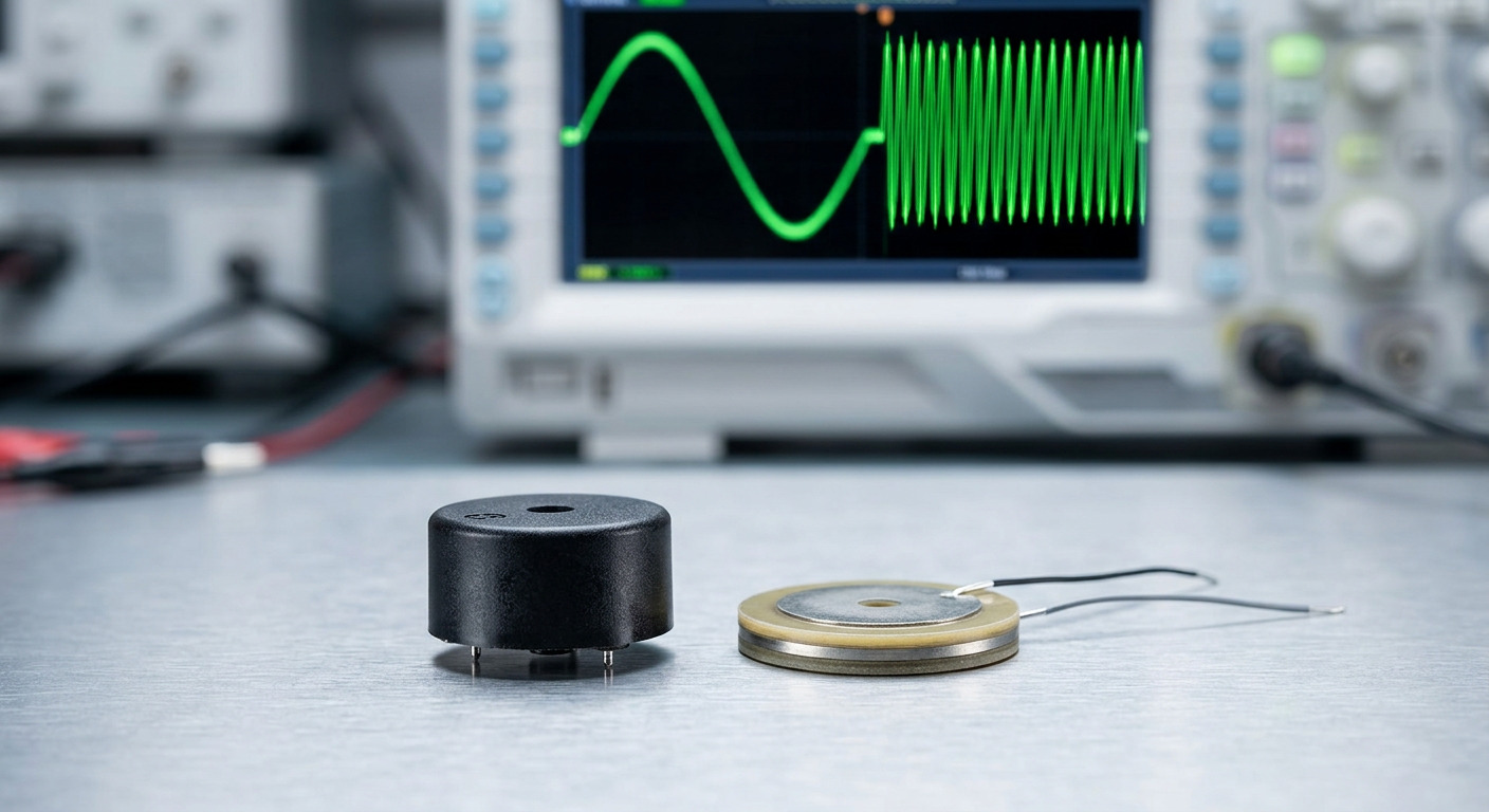
Both technologies are mechanical resonators, so both are loudest at one frequency and fall away either side. But they resonate in different bands, and the bands sound different.
Magnetic buzzers typically resonate between 1 kHz and 3 kHz. In that region output reads as fuller and less aggressive, which is why automotive chimes and appliance alerts often use them. The lower frequency also diffracts around obstacles more readily, so coverage in an obstructed space can be better than the numbers suggest.
Piezo buzzers typically resonate between 2.5 kHz and 4 kHz. That band sits close to the peak of human hearing sensitivity, which is exactly why it reads as urgent and penetrating. The BP1770-40 resonates at 4000 ± 500 Hz; the ultra-thin BP9019S-40 in a 9.0 × 1.9 mm body is specified for a 4 kHz square wave drive and produces a minimum of 65 dB at 10 cm at 3 Vp-p — a reminder that thin parts trade output for size.
The engineering point is that resonant frequency matters more than peak loudness. A buzzer driven off resonance can lose several dB while drawing identical current, so the drive frequency and the element's resonant band have to be matched deliberately. In a finished enclosure the assembled resonant frequency also shifts, which is one reason a passive part can outperform an active one: you can move the drive frequency to follow the cavity.

A magnetic buzzer contains a coil, and a coil carrying an alternating current is an electromagnetic radiator. The field is local and modest, but it is real, and it is the reason magnetic buzzers need layout attention: keep the buzzer and its current loop away from high-impedance analogue traces, away from radio antennas, and away from any magnetic sensing. Decoupling at the driver and a tight return path are the standard mitigations.
A piezoelectric element has no coil and no magnetic circuit, so it produces negligible EMI. This is a structural property rather than a design achievement, and it is why piezo parts can be placed directly beside a radio module, a Hall sensor or a precision analogue front end without shielding, spacing rules or a re-test.
If your product has an EMC test in its future and an acoustic alert in its specification, this difference alone can justify the piezo choice. Adding a shield or re-spinning a board to move a buzzer away from a sensor usually costs more than the price difference between the two technologies.
Everything above describes the transducer. Active and passive describes the drive, and the two choices are independent — there are active piezo buzzers, passive piezo buzzers, active magnetic buzzers and passive magnetic buzzers, and they are genuinely different products.
An active buzzer contains its own oscillator. Apply DC within the rated window and it produces a continuous tone at its design frequency. This removes a timer channel from your firmware and removes the risk of the tone drifting when you change the clock tree. The BPC2312W100-1235 active piezo buzzer shows what this looks like on a datasheet: 12 V DC rated across an 8–15 V range, at or below 20 mA, above 95 dB at 10 cm, continuous tone at 3500 ± 500 Hz, with wire leads and a 4.2 g body.
A passive buzzer is the transducer alone. Frequency, duty cycle and envelope all come from the signal you supply, which gives you multi-stage alarms, custom patterns and the ability to tune to the enclosure — at the cost of a timer resource and a more careful driver.
Table 2: Choosing the Configuration
Requirement | Active | Passive |
|---|---|---|
One fixed warning tone | Best fit | Works, but wastes capability |
Multiple alert stages or patterns | Two parts or a redesign | Best fit |
No spare timer channel in firmware | Best fit | Not viable |
Tuning to the finished enclosure | Not possible | Best fit |
Fastest bring-up | Best fit | Requires waveform validation |
Lowest component cost at volume | Slightly higher | Lower |

Table 3: Application Fit
Application | Preferred technology | Reason |
|---|---|---|
Battery-powered IoT and wearables | Piezo, small passive | Lowest current, no coil, thinnest bodies |
Smart utility meters | Piezo passive | Low current over a long service life |
Automotive chimes and dashboards | Magnetic | Low voltage, softer tone in the 1–3 kHz band |
Medical monitors and diagnostic equipment | Piezo | Negligible EMI near sensitive front ends |
Security panels and access control | Either; active for simplicity | Single unmistakable tone, DC drive |
Industrial machine alerts | Piezo, panel-threaded | High output, sealed bodies, wide voltage window |
Low-voltage consumer electronics | Magnetic | Works directly from 1.5–5 V rails |
Read the table as a starting point rather than a rule. The two constraints that override everything else are the supply rail and the available board area. If your rail is 1.8 V or 3.3 V, the magnetic option is usually the practical one. If your rail is 12 V or 24 V and board area is tight, the piezo option wins on current, thickness and EMI simultaneously.
The seven differences between a piezo buzzer and a magnetic buzzer are all consequences of one structural choice: whether the part uses a ceramic element or a coil. Mechanism, wear, voltage window, current draw, load type, resonant band and EMI footprint follow from it in a straight line.
For design work, the decision sequence is short. Establish the supply rail first, because it eliminates one technology in most cases. Establish the current budget second, because it eliminates the other in battery-powered products. Then choose active or passive based on whether the tone carries information, and finally pick a body size and mounting that suits the enclosure.
Before you commit, confirm four values in writing with your supplier: the sound pressure level with its distance and drive voltage, the resonant frequency and its tolerance, the current draw under your actual drive conditions, and the RoHS documentation for the exact part number. These are the four numbers most often quoted without conditions in catalogue copy, and the four that determine whether the finished product sounds the way the prototype did.
Choosing between piezoelectric and electromagnetic for a new design? TAT Electronics manufactures both technologies across SMD, pin-mount, wire-lead and panel-threaded formats, from 9 mm bodies up to 43 mm sealed units, with custom frequencies and wire assemblies available. Send your supply rail, target sound pressure level with its distance, and enclosure constraints through our contact page and we will come back with the closest matching part and a sample plan.
A: No. Loudness depends on the drive voltage, the resonant frequency match and the acoustic cavity, not on the technology alone. What the piezo technology reliably offers is more output per milliamp, because the element is capacitive and draws little steady current. A magnetic buzzer on a 5 V rail can be perfectly loud for a panel alert; it simply costs more current to get there. Compare candidates at the same distance and the same drive voltage, and the ranking can reverse.
A: Not safely. A magnetic buzzer draws tens of milliamps continuously while sounding, which is at or beyond the continuous rating of a typical GPIO pin, and the coil's collapsing field produces a voltage spike when the driver switches off. Use a transistor — BJT or MOSFET — with a flyback diode across the coil. A passive piezo is more forgiving on current, but it still needs a stage that can both source and sink charge to reach its rated output.
A: Because a passive piezo is driven by a waveform, not by a DC level. The peak-to-peak figure describes the full swing the element sees, so a 5 Vp-p square wave swings from 0 to 5 V, while a bridge drive can produce twice that swing from the same rail. Active piezo buzzers, which contain their own oscillator, are usually specified with both a rated DC voltage and an operating window, because that is what the user applies.
A: Noticeably, and roughly in proportion to the drive amplitude rather than in a straight dB-per-volt line, because the element's displacement scales with applied field. A piezo part specified at 24 V will not reach its catalogue figure on a 12 V rail, and the shortfall is usually larger than a simple halving would suggest. Always ask for the sound pressure level at your actual rail, or specify at the lowest voltage your supply can present.
A: Effectively, for practical purposes, yes. A piezo element has no coil and no magnetic circuit, so it does not radiate a magnetic field the way an electromagnetic buzzer does. The driver circuit still switches current and can radiate if it is laid out badly, so the correct statement is that the transducer contributes negligible EMI, which is what allows it to sit directly beside radio modules and precision sensors without shielding.


