
English 
Dedicated to global electroacoustic technology.
Views: 0 Author: Site Editor Publish Time: 2026-10-22 Origin: Site


The line between a micro speaker and a mini speaker is drawn at roughly 16 mm, and it is a line that matters more than the naming suggests. Below it, you are placing a transducer inside a product that was never designed around audio — a wearable, a smart lock, a medical monitor — and the constraints are board area, thickness and current. Above it, you are designing a product that has room for an acoustic cavity, and the constraints become sensitivity, low-frequency output and how the enclosure loads the driver. Both categories use mylar diaphragms and both are specified the same way on a datasheet, which is why they get confused. This guide sets out the five differences that actually decide which one belongs in your design.
Size is the whole distinction, and it sets everything else: A micro speaker is a sub-16 mm driver for in-enclosure signalling and voice prompts. A mini speaker is a 20–57 mm driver with room for a real acoustic cavity. Diameter determines diaphragm area, and diaphragm area determines how much air the part can move.
Low-frequency output follows diaphragm area, not power handling: A 13 mm part cannot produce meaningful output below its resonance. Increasing input power on a small driver produces excursion, distortion and heat, not bass.
Sound pressure level is quoted at a drive level, and the drive levels differ: Sensors in TAT's range are specified at 0.5 W / 10 cm in the 13–23 mm sizes, and at 0.1 W / 10 cm for the 57 mm size. Convert before comparing.
Impedance is a matching decision, not a quality decision: The 32 Ω parts suit low-voltage, current-limited supplies; the 8 Ω and 4 Ω parts extract more power from a given amplifier. Getting this wrong wastes amplifier headroom or overheats the driver.
Thickness is the constraint that rules out whole product categories: A 13 mm driver is thin, but a 36 mm ultra-thin mylar part achieves a 2–4 mm profile with a 500 Hz–10 kHz band — which is why it appears in devices that cannot fit a conventional 36 mm speaker.
The enclosure is part of the specification: A mini speaker's rear volume and porting are as much a part of its performance as its magnet. A micro speaker has less room to tune, so the design work moves into the housing tolerance and the gasket.
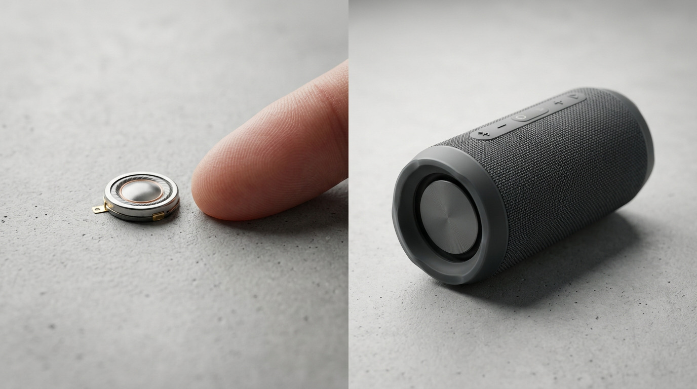
There is no formal standard, but the practical boundary is set by what the part can do rather than by its diameter. In TAT's range the split falls between 13 mm and 20 mm:
Table 1: Micro and Mini Speakers Compared Across the Range
Model | Diameter | Frequency range | Sound pressure level | Impedance | Rated power |
|---|---|---|---|---|---|
TATSP13A-002 | 13 mm | F0 to 5 kHz | 88 ± 3 dB at 0.5 W / 10 cm | 32 ± 20 % Ω | 0.5 W normal, 1.0 W max |
TATSP20B-001 | 20 mm | F0 to 20 kHz | 95 ± 3 dB at 0.5 W / 10 cm | 8 ± 20 % Ω | 0.5 W normal, 1.0 W max |
TATSP23A-001 | 23 mm | F0 to 20 kHz | 93 ± 3 dB at 0.5 W / 10 cm | 8 ± 15 % Ω | 0.5 W normal, 0.7 W max |
S36 ultra-thin | 36 mm | 500 Hz to 10 kHz | — | 4 Ω or 8 Ω | 0.5 W to 2 W |
TAT-S57F2-8-1 | 57 mm | F0 to 10 kHz | 82 ± 3 dB at 0.1 W / 10 cm | 8 ± 15 % Ω | 0.5 W to 1 W |
Read that table top to bottom and a pattern appears that is not obvious from the numbers alone. The 13 mm part stops at 5 kHz and 32 Ω. The 20 mm and 23 mm parts reach 20 kHz and drop to 8 Ω. The 36 mm part trades bandwidth for thickness — 2–4 mm profile, 500 Hz to 10 kHz. The 57 mm part is the widest physically but is specified at a fifth of the drive power, which is why its sound pressure figure looks lower.
One clarification before going further, because the term is used two ways in the market. A "mini speaker" in consumer retail usually means a small self-contained Bluetooth product — a driver, an amplifier, a battery and an enclosure in one box. What an engineer actually specifies is the driver inside it, and that is the sense used here: a 20 mm to 57 mm mylar speaker component. The two meanings point at the same physics. The retail product is loud and bass-capable because it contains a larger driver and a designed cavity, and the component-level question is which of those you can afford in your enclosure.
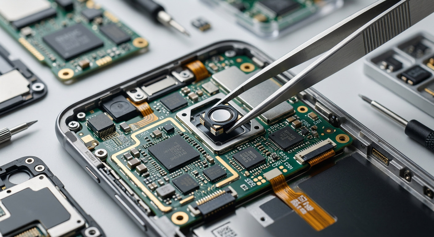
A micro speaker's defining property is that it goes where nothing else fits. A 13 mm driver on a 32 Ω coil, or a 36 mm ultra-thin part at 2–4 mm thick, lets you put audio into a wearable, a smart lock, a handheld instrument or a medical monitor without redesigning the enclosure around it.
That constraint cuts both ways. Board area is only part of it — the real limit is often the sound path. A micro speaker needs a sealed rear chamber and a clear path to the outside, and in a device the size of a smart lock both are measured in millimetres. Any leak between the front and the back of the diaphragm cancels low-frequency output, which is why gasket design matters more than driver choice at this scale.
A mini speaker has room to solve those problems. A 20 mm or 23 mm part still fits a compact enclosure but allows a real rear volume and a defined port, so the acoustic design has parameters you can tune. The 57 mm part goes further: it needs a housing designed around it, with a defined cavity and a mounting frame, and in exchange it moves enough air to produce recognisable low frequencies.
The practical rule: if the mechanical design is already frozen, you are choosing a micro speaker. If the mechanical design is still open and audio quality matters, the mini speaker options are available and worth the enclosure work.
Low-frequency output requires moving air, and moving air requires diaphragm area and excursion. Both scale with diameter, so the difference between a 13 mm and a 57 mm driver is not a matter of tuning — it is roughly a factor of nineteen in radiating area.
That has three consequences that are worth stating plainly, because they are the most frequent source of disappointment in compact audio projects.
First, no amount of amplifier power fixes a small driver. Increasing the input to a 13 mm part at 200 Hz produces excursion and distortion long before it produces audible bass, and in the worst case it drives the voice coil out of the gap. The rated power figure is a thermal and mechanical limit, not a target.
Second, the resonant frequency sets the floor of useful output. The 13 mm part resonates at 600 ± 20 % Hz; the 20 mm at 650 ± 20 % Hz; the 23 mm at 750 ± 20 % Hz; the 57 mm is specified across F0 to 10 kHz without a single resonant figure because the band, not a point, is what matters for a full-range driver. Below resonance, output falls away quickly in every case.
Third, for voice, the low end is not where the information is. Speech intelligibility lives largely between 500 Hz and 4 kHz. A 13 mm driver covering F0 to 5 kHz with a 600 Hz resonance is a reasonable voice prompt device, and its limited bass is irrelevant to the task. Judging it against a music playback standard is the wrong test.
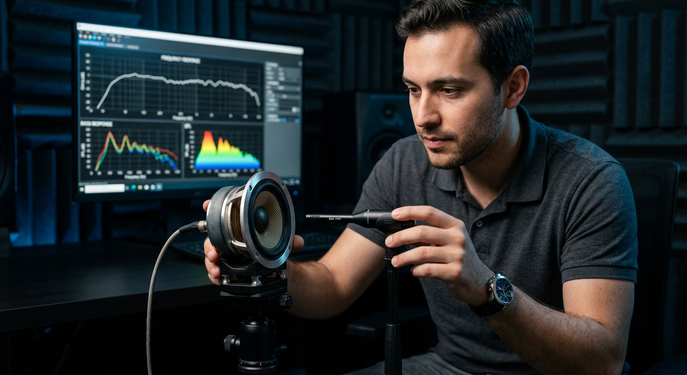
Sound pressure level is the number most often compared and the number most often compared wrongly, because the drive condition travels with it.
In TAT's range, the 13 mm, 20 mm and 23 mm parts are all specified at 0.5 W input, measured at 10 cm, with the figure averaged across 0.8, 1.0, 1.2 and 1.5 kHz. Under those identical conditions they come out at 88 ± 3 dB, 95 ± 3 dB and 93 ± 3 dB respectively. Note that the 20 mm part is specified higher than the 23 mm part — measurement conditions and design intent, not size, produce that ordering, and it is a reminder not to assume monotonic improvement with diameter.
The 57 mm part is specified at 82 ± 3 dB but at 0.1 W, one fifth of the drive power used for the smaller parts. Quote it at 0.5 W and the figure would rise by roughly 7 dB. This is exactly the kind of comparison trap that leads to a larger driver being specified unnecessarily.
Four factors move the figure besides the driver itself: drive power at roughly 3 dB per doubling, measurement distance at roughly 6 dB per doubling, the band over which the measurement is averaged, and the enclosure. That last one is the largest uncontrolled variable in a real product — a rear volume that is too small, or a gasket leak that lets front and rear pressure cancel, can cost more output than the difference between two driver sizes.
The rule that follows is to ask three questions of any figure before using it: at what power, at what distance, and over what band. A supplier who cannot answer all three has not given you a specification.
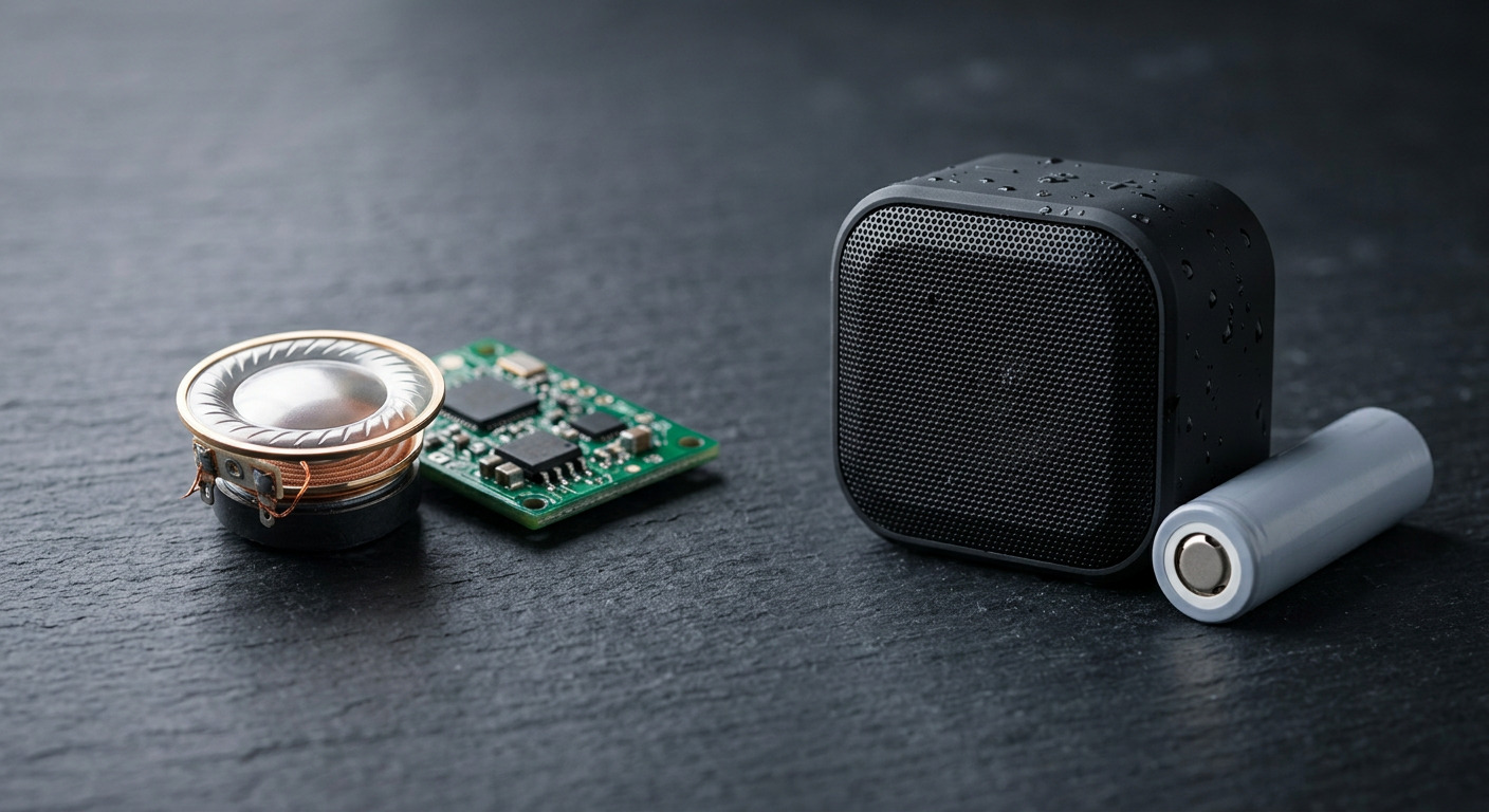
Impedance decides how much current the driver demands for a given voltage, and therefore how much of your amplifier's capability you can actually use.
The 32 Ω parts are the low-current choice. At 3.3 V a 32 Ω driver draws on the order of 100 mA peak, which suits a small amplifier running from a logic rail or a modest battery. Sensitivity is lower for the same voltage, so these parts are usually paired with a dedicated amplifier rather than driven from a filtered PWM pin.
The 8 Ω parts extract more power from a given amplifier at the cost of drawing more current. At 3.3 V an 8 Ω driver would demand over 400 mA for full swing, which in practice means either a higher supply rail or an amplifier with a boost converter. In TAT's range the 8 Ω option appears from 20 mm upward — the 20 mm TATSP20B-001, the 23 mm TATSP23A-001 and the 57 mm TAT-S57F2-8-1 — while the 13 mm part uses 32 Ω. The 36 mm ultra-thin part offers either 4 Ω or 8 Ω.
Table 2: Impedance and Supply Choice
Impedance | Typical supply | Amplifier implication | Suits |
|---|---|---|---|
32 Ω | 3.3 V to 5 V logic rail | Modest current, small Class-D | Wearables, handhelds, medical monitors |
8 Ω | 5 V, or 3.3 V with boost | Higher current, more headroom | Smart home panels, appliances, kiosks |
4 Ω | 5 V and above | Highest current, best power transfer | Larger enclosures, louder output |
Matching is not about quality; it is about not wasting what you have. A 32 Ω driver on an amplifier designed for 8 Ω will be quiet. An 8 Ω driver on an amplifier designed for 32 Ω will clip and overheat. Either way the fix is at the schematic stage, not in the acoustic design.
All of the parts described here use a polyester film diaphragm — mylar — rather than paper. That choice is not cosmetic. Mylar is moisture resistant, dimensionally stable, and consistent from unit to unit, which matters when the same product is built in volume over several years.
The material also enables the thickness that makes the category possible. The 36 mm ultra-thin part achieves a 2–4 mm profile with a 500 Hz–10 kHz band, which is what allows a driver of that diameter to go into a flat device. Paper cones cannot be made reliably at that thickness with that consistency.
Table 3: Material and Durability
Property | Mylar (polyester film) | Paper |
|---|---|---|
Moisture resistance | Good, inherently | Poor, warps and softens |
Consistency unit to unit | High | Variable |
Achievable thickness | Very thin profiles | Limited |
Temperature range | Model-dependent, e.g. −30 to +50 °C or −20 to +60 °C | Narrower in practice |
Acoustic character | Neutral, slightly forward | Warmer in the midrange |
The temperature figures are worth quoting exactly because they differ by part and they are frequently assumed rather than checked. The 23 mm part is rated −30 to +50 °C; the 57 mm part is rated −20 to +60 °C. Neither is a wide-temperature part in the industrial sense, which is why outdoor products need the driver protected inside the enclosure rather than exposed.
For expected life, the 36 mm ultra-thin part is specified at 20 000 to 30 000 hours and is declared RoHS compliant. Those two pieces of documentation — the life figure and the compliance declaration for the exact part number — are worth requesting explicitly, because they are the ones most often missing from a quotation.
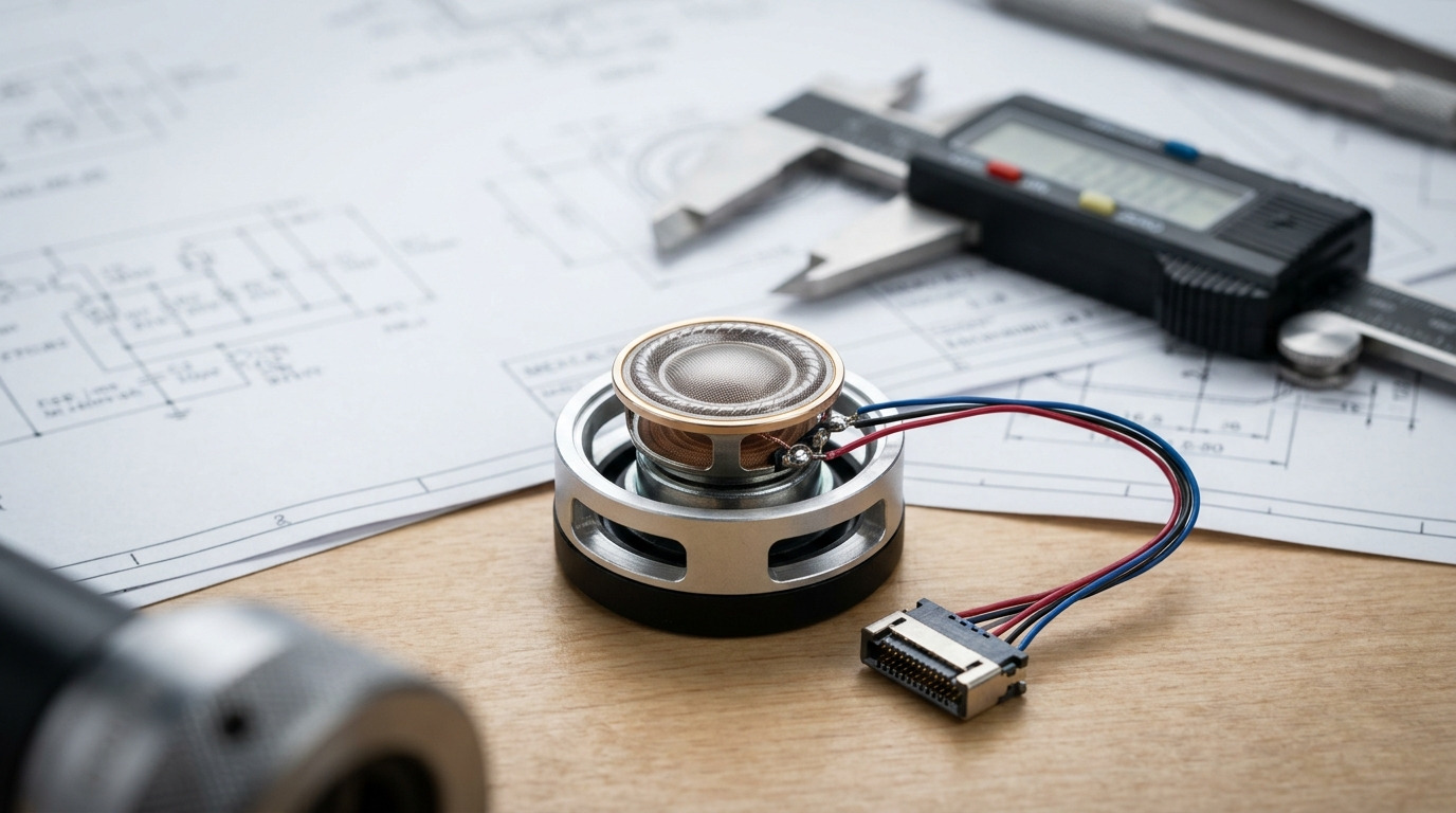
A speaker datasheet is short but every line changes a design decision. The five that matter most:
Resonant frequency (F0) sets the floor of useful output. Below it, output falls away and excursion rises. If your content is voice starting at 500 Hz, a part with F0 at 600 Hz is a reasonable fit; a part with F0 at 750 Hz will need the lower band filtered or accepted.
Frequency range is the band over which the part is specified, not the band over which it is flat. F0 to 20 kHz on a 20 mm driver does not mean flat response across that span; it means the part operates across it. Ask for a curve if the shape matters.
Sound pressure level with its drive power, distance and measurement band, as discussed above.
Impedance with tolerance and the frequency at which it is measured. A 32 ± 20 % Ω figure at 1 kHz is not the impedance at 200 Hz, and the difference matters for amplifier design.
Rated and maximum power, remembering that the maximum is a limit rather than an operating point.
Two further items are easy to overlook: the operating temperature range, and the connector or lead configuration. The second one determines whether the part can be assembled onto your line without hand soldering, which is often the deciding factor at volume.

For anything where the enclosure is fixed and the task is signalling or short voice prompts — smart locks, wearables, medical monitors, handheld instruments — the micro speaker is the right starting point. The 13 mm, 32 Ω part suits low-voltage supplies and tight boards; the 36 mm ultra-thin part suits flat devices that need more output than a 13 mm can give without more thickness.
For anything with room to design a cavity — smart home panels, appliances, kiosks, access control units, small public-address devices — the 20 mm and 23 mm parts give a better balance of output, bandwidth and enclosure tolerance. The 8 Ω impedance suits a 5 V amplifier with real headroom.
For the largest compact enclosures, the 57 mm part produces recognisable low frequencies and works for music and multimedia prompts, at the cost of a housing designed around it and a temperature limit of +60 °C.
A sensible default for a new product: start with the 20 mm, 8 Ω part, design a rear volume you can vary, and measure. Resize from there rather than from a specification table, because the enclosure contributes several decibels either way and the only way to know which way is to test. The full mylar speaker range is the place to compare diameters, impedances and thicknesses side by side.
The difference between a micro speaker and a mini speaker is size, and size determines diaphragm area, which determines low-frequency output, which determines what the product can credibly reproduce. Everything else — impedance, power handling, diaphragm thickness, temperature range — follows from that and from the design intent of the specific part.
Three practical rules summarise the choice. Judge a micro speaker on voice intelligibility, not on music. Compare sound pressure figures only at the same drive power and distance. And treat the enclosure as part of the acoustic design rather than as packaging, because at this scale the rear volume and the gasket contribute as much as the driver.
Before release, confirm four things in writing for the exact part number: the sound pressure level with its drive power and distance, the frequency range with the resonant point, the impedance with its measurement frequency, and the RoHS declaration. These determine whether the finished product performs the way the sample did.
Choosing between a micro and a mini speaker for a compact product? TAT Electronics manufactures mylar speakers from 13 mm to 57 mm in 4 Ω, 8 Ω and 32 Ω versions, including a 2–4 mm ultra-thin profile for flat devices, with custom wire assemblies, connectors and housing-matched acoustic cavities. Send your enclosure volume, supply rail, target sound pressure level and frequency band through our contact page and we will come back with the closest matching part and a sample plan.
A: In practice the boundary sits at roughly 16 mm, and it is defined by what the part can do rather than by a standard. A micro speaker is a sub-16 mm driver intended for in-enclosure signalling and short voice prompts, where the constraints are board area, thickness and current. A mini speaker is a 20–57 mm driver that has room for a real acoustic cavity, so its design is driven by sensitivity, low-frequency output and how the enclosure loads it. Both use mylar diaphragms and both are specified the same way.
A: Not meaningfully. A 13 mm part in TAT's range resonates at 600 ± 20 % Hz and is specified across F0 to 5 kHz, so output below its resonance falls away quickly. Adding amplifier power does not fix this: excess input drives excursion and distortion rather than low-frequency output, and can push the voice coil out of its gap. For music or recognisable bass you need the diaphragm area of a 20 mm or larger part, and for real low-frequency output a 57 mm driver in a designed enclosure.
A: Convert both to the same drive power and the same distance first. In TAT's range the 13 mm, 20 mm and 23 mm parts are all specified at 0.5 W / 10 cm, so those figures are directly comparable at 88 ± 3 dB, 95 ± 3 dB and 93 ± 3 dB. The 57 mm part is specified at 0.1 W / 10 cm at 82 ± 3 dB, and quoting it at 0.5 W would raise the figure by roughly 7 dB. Power scales at about 3 dB per doubling, and distance at about 6 dB per doubling.
A: Not directly, but it affects how much of your amplifier's capability reaches the driver, which is often mistaken for a quality difference. A 32 Ω part draws less current at a given voltage and suits low-voltage supplies and current-limited designs. An 8 Ω or 4 Ω part extracts more power from a given amplifier at the cost of higher current, and usually needs a higher rail or a boosted supply. Mismatching wastes headroom in one direction or overheats the driver in the other.
A: Because the ultra-thin versions are designed around a mylar film diaphragm rather than a conventional cone and surround. Mylar can be made thin and consistent enough to achieve a 2–4 mm profile while still covering a usable band — the 36 mm ultra-thin part in TAT's range is specified at 500 Hz to 10 kHz at 0.5 W to 2 W in 4 Ω or 8 Ω. That profile is what allows a driver of that diameter to fit into a flat device, which conventional construction cannot achieve.


