
English 
Dedicated to global electroacoustic technology.
Views: 0 Author: Site Editor Publish Time: 2026-08-03 Origin: Site


Hardware designers constantly face a frustrating engineering dilemma. Selecting an audio alert component requires balancing desired Sound Pressure Level (SPL) and tone against strict power budgets, PCB real estate, and target constraints. You must ensure the device is loud enough to be heard but efficient enough to survive on limited battery capacity. Both piezo and magnetic buzzers achieve the same functional outcome. They generate sound to alert users. However, their underlying mechanics dictate entirely different electrical and physical requirements. A misstep here can drain batteries prematurely or require extensive board redesigns late in the development cycle. This guide provides a direct, data-driven comparison of both technologies. You will learn exactly how these components operate at a physical level. We will explore their specific power consumption profiles and footprint demands. Finally, you will gain a practical framework to help select the correct buzzer architecture for your specific application constraints.
Piezo buzzers operate on high voltage and minimal current, making them ideal for high-SPL applications and battery-powered (low-draw) devices.
Magnetic buzzers operate on low voltage and higher current, producing lower-frequency, subjectively "warmer" tones suited for consumer electronics and compact PCB layouts.
The choice ultimately hinges on three constraints: available drive voltage, acceptable current consumption, and physical space requirements.
Both technologies are available as indicators (internal drive circuit) or transducers (requiring external drive signals).
To make an informed choice, you must understand how these components convert electrical energy into acoustic energy. The physical mechanisms are entirely different.
A Piezo Buzzer relies on the piezoelectric effect. Manufacturers bond a thin piezoceramic element to a flat metal plate. You apply an alternating voltage across this ceramic material. The electrical field causes the ceramic layer to rapidly expand and contract. Because it attaches securely to the metal disk, this motion forces the metal plate to bend back and forth. This rapid bending pushes the surrounding air. The air movement creates audible sound waves. There are no moving mechanical coils involved. The entire assembly flexes as a single unit.
Conversely, magnetic variants use a traditional voice-coil approach. You will find a wire coil wrapped around a central bobbin inside the housing. An alternating current passes through this wire coil. This current creates a fluctuating magnetic field. Above the coil sits a thin ferromagnetic disk. The fluctuating magnetic field rapidly attracts and releases this metal disk. The disk vibrates up and down, pushing air to generate sound waves. This mechanism mimics a traditional stereo speaker on a much smaller scale.
These distinct physical mechanisms dictate their electrical behavior in your circuit. The piezoelectric element acts primarily as a capacitive load. It requires high voltage to create a strong electric field, but it draws very little actual current. The electromagnetic voice coil acts as an inductive load. It requires a heavy flow of current to generate a strong magnetic field, but it operates effectively at much lower voltages. Understanding this distinction prevents disastrous circuit design errors.
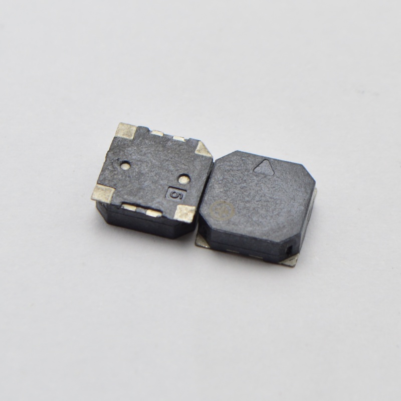
Engineers evaluate audio alerts across three main dimensions. Your final decision will depend on how your project prioritizes power, acoustics, and physical space.
Power availability is often the most rigid constraint in hardware design. Piezo units are famous for their incredibly low current draw. They typically consume under 10mA during active operation. Many small units draw as little as 3mA. However, they require higher operating voltages to achieve maximum SPL. You might need anywhere from 3V up to 100V+ to drive them loud enough for industrial applications. Designers often use charge pumps or step-up converters to boost the voltage.
Magnetic models present the opposite power profile. They function exceptionally well on lower operating voltages. You can typically drive them directly from 1.5V to 12V rails. They easily run on standard 3.3V or 5V logic levels. However, they require significantly higher current to generate their magnetic field. They often draw anywhere from 20mA to 100mA+. This high current draw can strain small voltage regulators or drain small batteries rapidly.
Acoustic requirements vary wildly depending on the end user. Piezo diaphragms naturally resonate at higher frequencies. They generally perform best between 2kHz and 4kHz, though some go much higher. This yields a very sharp, piercing sound. High SPL at these high frequencies cuts through ambient background noise easily. This makes them ideal for critical life-safety alarms. Smoke detectors, carbon monoxide monitors, and industrial machinery alerts rely heavily on them.
Magnetic diaphragms tend to resonate at lower frequencies. Their optimal range usually falls between 1.5kHz and 3kHz. This lower frequency produces a less abrasive, lower-pitched tone. Many users describe the sound as warmer or less aggressive. This profile is highly preferred for standard user interface feedback. You will hear this tone in microwave ovens, washing machines, toys, and desktop consumer gadgets.
PCB real estate dictates what components you can actually fit inside the enclosure. Piezo components typically require a larger footprint diameter. The metal disk needs sufficient surface area to flex and achieve lower resonant frequencies. Fortunately, manufacturers can produce them with an exceptionally thin vertical profile. They fit perfectly into flat, slim enclosures where Z-axis height is restricted.
Magnetic units generally require less surface area. They feature a smaller footprint diameter, saving horizontal space on your PCB. However, they demand a taller vertical profile. The housing must physically accommodate the internal magnet, the wire coil, and the bobbin assembly. You must ensure your product enclosure has enough vertical clearance to house them safely.
Table 1: Quick Comparison Guide
Feature | Piezo Technologies | Magnetic Technologies |
|---|---|---|
Current Draw | Very Low (Typically <10mA) | High (Typically 20mA - 100mA+) |
Operating Voltage | High (Often 3V - 100V+) | Low (Often 1.5V - 12V) |
Frequency Range | Higher (2kHz - 4kHz+) | Lower (1.5kHz - 3kHz) |
Sound Profile | Sharp, piercing, high SPL | Warmer, lower-pitched, smoother |
Form Factor | Wider diameter, very thin profile | Smaller diameter, taller profile |
Load Type | Capacitive Load | Inductive Load |
You must select a drive type regardless of the underlying sound generation technology. Both piezo and magnetic models are available in two distinct configurations. They are categorized strictly by their drive types.
An indicator contains a built-in oscillating circuit directly inside the housing. The concept is incredibly straightforward. The manufacturer integrates the complex waveform generation circuitry for you. Implementation requires very little engineering effort. You only need to apply a continuous DC voltage across the pins. The component will immediately emit a continuous tone at a fixed frequency. This is highly convenient for simple project designs.
However, this convenience comes with strict limitations. Indicators offer absolutely no flexibility over the frequency or pitch. You cannot play melodies. You cannot change the tone to indicate different error states. You can only turn the fixed sound on or off. If you pulse the DC power, you can create a simple beeping effect, but the pitch remains identical.
A transducer completely lacks internal circuitry. It contains only the raw acoustic generating element. Implementation requires an external oscillating signal to function. You must supply a specific AC voltage or a square wave signal. Engineers typically use a PWM (Pulse Width Modulation) pin from a microcontroller to drive them. This requires more hardware design effort and software coding.
The primary advantage is complete acoustic control. You dictate the exact frequency of the signal. This allows you to generate complex audio profiles. You can program varying pitches, sweeping sirens, or custom melodies. If your product needs to play different tunes for different alerts, you must select a transducer.
Choosing the wrong audio component can introduce severe bugs into your hardware. You must evaluate these three critical design considerations before finalizing your bill of materials.
A Magnetic Buzzer acts as an inductive load due to its internal wire coil. If you drive it externally as a transducer, it presents a significant electrical risk. When the driving transistor switches off, the magnetic field rapidly collapses. This collapse induces a massive reverse voltage spike. We call this flyback voltage. If unmitigated, this spike will travel back to your microcontroller and permanently damage the silicon. You must protect the circuit. Always place a flyback diode in parallel across the inductive coil to safely dissipate this energy. Piezo components are capacitive. They generally do not present this inductive voltage spike risk, simplifying circuit protection.
Many devices operate in harsh environments. Dust, moisture, and extreme temperature fluctuations destroy sensitive components. Piezo units hold a distinct advantage here. They can often be fully sealed during manufacturing. Because they have no internal coils or separated moving parts in the traditional sense, a sealed housing does not impede their function. This makes them inherently more resistant to environmental damage. Magnetic units require small openings for the diaphragm to move air effectively. They are much harder to waterproof fully, making them vulnerable in outdoor applications.
Battery-operated systems face ruthless power constraints. Remote IoT sensors, smart wearables, and portable medical devices rely on tiny lithium coin cells. Every milliamp matters. The high current draw of a magnetic voice coil can rapidly deplete battery life. A single prolonged alarm might cause a brownout in the system. Therefore, piezo technology is the default choice for ultra-low-power devices. Their minimal current consumption ensures the device can sound an alert without immediately killing the battery.
Selecting the optimal component does not have to be guesswork. Follow a systematic approach. Evaluate your power budget first. Next, review your available PCB volume. Finally, define the exact user experience you want the sound to deliver. We recommend using the following guidelines to narrow down your choices.
Define the Power Source: Determine if the system runs on a small battery or wall power. Note the available voltage rails.
Calculate Space Limits: Measure the maximum allowable diameter on the PCB and the maximum vertical clearance inside the plastic enclosure.
Determine Acoustic Goals: Decide if the alert needs to wake someone up from sleep or simply acknowledge a button press.
Select the Drive Method: Choose between simple continuous tones (indicator) or complex programmable melodies (transducer).
The device is battery-powered and requires ultra-low current consumption to maximize lifespan.
The application demands a loud, piercing alarm, such as life-safety devices or industrial fault warnings.
There is ample PCB footprint diameter available, but vertical height inside the enclosure is strictly restricted.
The operational environment is harsh, and the product requires a fully sealed, highly durable component.
The system operates strictly on low voltage logic rails without the budget or space for a step-up voltage converter.
The desired audio feedback needs to be lower-pitched and less aggressive, common in microwave keypads or toys.
PCB space is severely limited in the X/Y axis for component placement, but ample Z-axis height is available.
The design relies on simple, low-voltage external driving circuitry where high voltage rails are absent.
The choice between these two acoustic technologies is rarely about one being objectively "better" than the other. It is always a precise calculation of voltage availability, power limitations, and acoustic requirements. Piezo technology excels in high-efficiency, high-volume scenarios. Magnetic technology shines in low-voltage applications requiring smooth, lower-frequency feedback. Review your project constraints against the profiles discussed above to ensure optimal performance.
For your next steps, we strongly recommend hardware designers test samples directly in their actual physical enclosures. The plastic acoustic cavities of your final product heavily influence the final SPL and perceived tone. A component that sounds perfect on a bare PCB may sound entirely different once encased. Please consult our catalog and data sheets for detailed specifications, or reach out to our engineering team for specialized consultation on custom acoustics.
A: It depends on the MCU's voltage output and whether the component is an indicator or transducer. While some very low-voltage indicators might operate directly from a GPIO pin, transducers usually require more power. You often need a dedicated transistor or a specific driver IC to achieve the maximum specified volume.
A: Yes, absolutely. If you use a magnetic unit as a transducer driven by an external transistor, you must protect your circuit. The internal coil is an inductive load. The diode protects your sensitive microcontroller pins against damaging inductive voltage spikes.
A: This usually happens for two reasons. First, you might be supplying insufficient drive voltage compared to the testing parameters. Second, your final product casing likely lacks a proper acoustic chamber or Helmholtz resonator. The enclosure design drastically impacts the final acoustic output.
A: Piezo buzzers are significantly better for battery-operated devices. They act as capacitive loads and draw minimal current, usually under 10mA. This extremely low current consumption prevents rapid battery depletion during alarm events.


