
English 
Dedicated to global electroacoustic technology.
Views: 0 Author: Site Editor Publish Time: 2026-11-05 Origin: Site


A buzzer datasheet looks like the simplest document in a bill of materials. Eight or ten short lines, a drawing, and a tolerance. That simplicity is exactly what makes it dangerous. Unlike a resistor or a capacitor, an acoustic component's headline number is not a property of the part alone — it is a property of the part under a stated drive condition, measured at a stated distance. Strip that condition away and the number stops meaning anything.
This guide walks through the eight lines that actually decide whether a part works in your design, using the published parameter tables of four real parts from the TAT Electronics buzzer range: an internally driven piezo indicator, two externally driven piezo transducers, and an internally driven electromagnetic unit. Every figure quoted below is taken verbatim from those sheets, so you can open the same pages and follow along.
The first line engineers read is usually the rated voltage, and it is usually the one they misapply. Rated voltage is the reference point at which the manufacturer measured everything else on the sheet. It is a test condition, not a usable range.
The usable range is the line immediately below it. On the BPC2310 sheet, the rated voltage reads 12 VDC and the operating voltage reads 6 ~ 15 VDC. Those two lines answer different questions. The first says "we characterised this part at 12 V". The second says "the internal circuit will keep oscillating anywhere between 6 V and 15 V". If your rail is 9 V, you are inside the operating window and outside the rated point — the part will run, but no figure printed on the sheet describes what it will do there.
The BMC1265-0527 shows the same structure at a lower rail: rated 5VDC, operating 1 – 12 VDC. That is a 12:1 span on a 5 V part. It is real, and it is also a warning — an electromagnetic buzzer that still sounds at 1 V is sounding well below its characterised point, so the 85 dB at 10 cm headline does not apply at that end of the range.
One practical consequence: when a design review asks "will this part work at 3.3 V", the answer is not yes or no. It is a question back — at 3.3 V, which of the eight lines are you still relying on?
Current draw is the line most often compared across parts, and the comparison is almost always invalid, because the measurement conditions differ between active and passive devices.
Read the four sheets side by side:
Model | Type | Current line as printed | What the condition implies |
|---|---|---|---|
BPC2310 | Active piezo, internal drive |
| Steady DC draw while sounding |
BMC1265-0527 | Active electromagnetic, internal drive |
| Steady DC draw while sounding |
BP1440-40 | Passive piezo, external drive |
| Draw depends on your drive waveform |
BP1770C-0540 | Passive piezo, external drive |
| Draw depends on your drive waveform |
The two active parts state one condition: a DC voltage. The number is roughly what the part will pull continuously. The two passive parts state a drive waveform — frequency, duty cycle, and amplitude in volts peak-to-peak. For a passive piezo, current is dominated by the capacitive reactance of the ceramic element, so it rises with frequency and with amplitude. Change your PWM frequency and the current changes with it. The printed 5 mA is a data point on a curve, not a ceiling you can budget against.
This matters for battery-powered products in a specific way. If you budget 5 mA for a passive transducer and then drive it at twice the stated frequency, you have not exceeded a specification — you have left the region the specification describes. The part will draw more, and the sheet will not have been wrong.
The SPL line is the one buyers quote to each other, and it is the least portable number on the page. Three things must be pinned down before any dB figure can be compared: the measuring distance, the drive voltage, and — for passive parts — the drive waveform.
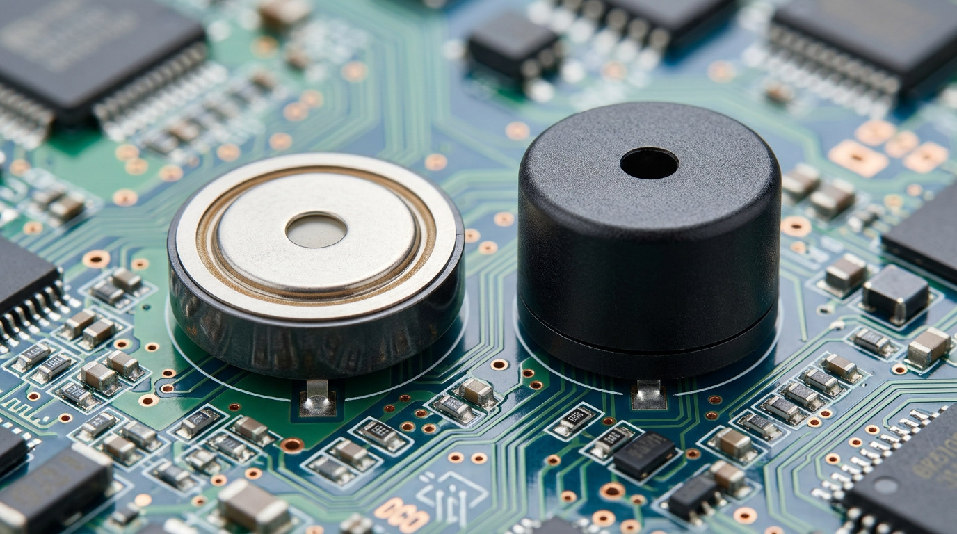
All four sheets here state the distance explicitly, which is a good sign: Min.90dB @12VDC and 10cm, 85 dB at 10 cm, Min.80dB @10cm,4KHz,50% duty Square Wave,5Vp-p, ≥ 85 dB at 10 cm, at 5 Vp-p. The distance is consistent at 10 cm across all four, so cross-reading is at least possible on that axis.
The drive conditions are not consistent, and they are not supposed to be. The BPC2310 reaches its Min.90dB on a 12 VDC rail. The BP1770C-0540 reaches ≥ 85 dB at 5 Vp-p — a peak-to-peak figure, which for a square wave means the signal swings from roughly +2.5 V to −2.5 V. Comparing "90 dB" to "85 dB" as if the two numbers sat on the same scale is a common and expensive mistake: they were produced by different electrical inputs, and the difference between them is partly the difference between 12 V and 5 V, not a difference in acoustic capability.
A second trap sits inside the passive sheets. The BP1440-40 quotes Min.80dB @10cm,4KHz,50% duty Square Wave,5Vp-p. Four conditions are printed in one line, and all four are load-bearing. Drive it at 5 Vp-p but at 3 kHz instead of 4 kHz and the output drops, because 4 kHz is the mechanical resonance the ceramic disc was tuned to. Drive it at 4 kHz but at a 30% duty cycle and the RMS energy delivered falls. The number is a coordinate, not a capacity.
Frequency lines look precise and are not. Read the tolerances:
Model | Resonant frequency as printed | Tolerance width |
|---|---|---|
BPC2310 |
| ±14.3 % |
BP1440-40 |
| ±12.5 % |
BP1770C-0540 |
| Not stated as a band |
BMC1265-0527 |
| ±11.1 % |
A ±500 Hz band on a 4000 Hz part is not a rounding artefact. It means a production unit may peak at 3500 Hz or at 4500 Hz, and the sheet is telling you that both are in specification. If your firmware emits a fixed 4000 Hz tone and the unit in front of you resonates at 4450 Hz, you are driving off-peak — output will be lower than the headline figure, and nothing on the sheet was violated.
The BP1770C-0540 sheet handles this differently, printing 4000 Hz (square wave drive) with the drive condition attached rather than a tolerance band. That phrasing is a reminder that for a passive piezo, "resonant frequency" is only meaningful when you name the waveform, because the element is driven, not self-oscillating.
The design implication is the same in both cases: if your product needs a consistent tone across a production run, a fixed-frequency drive on a wide-tolerance passive part is the wrong architecture. Either sweep the drive to find the peak at end-of-line test, or move to an internally driven part where the oscillator sits inside the housing and the pitch is set at the factory.
This is the line that is easiest to skim past and most expensive to get wrong, because it determines whether you need a timer at all. The unit tells you: VDC or Vp-p.
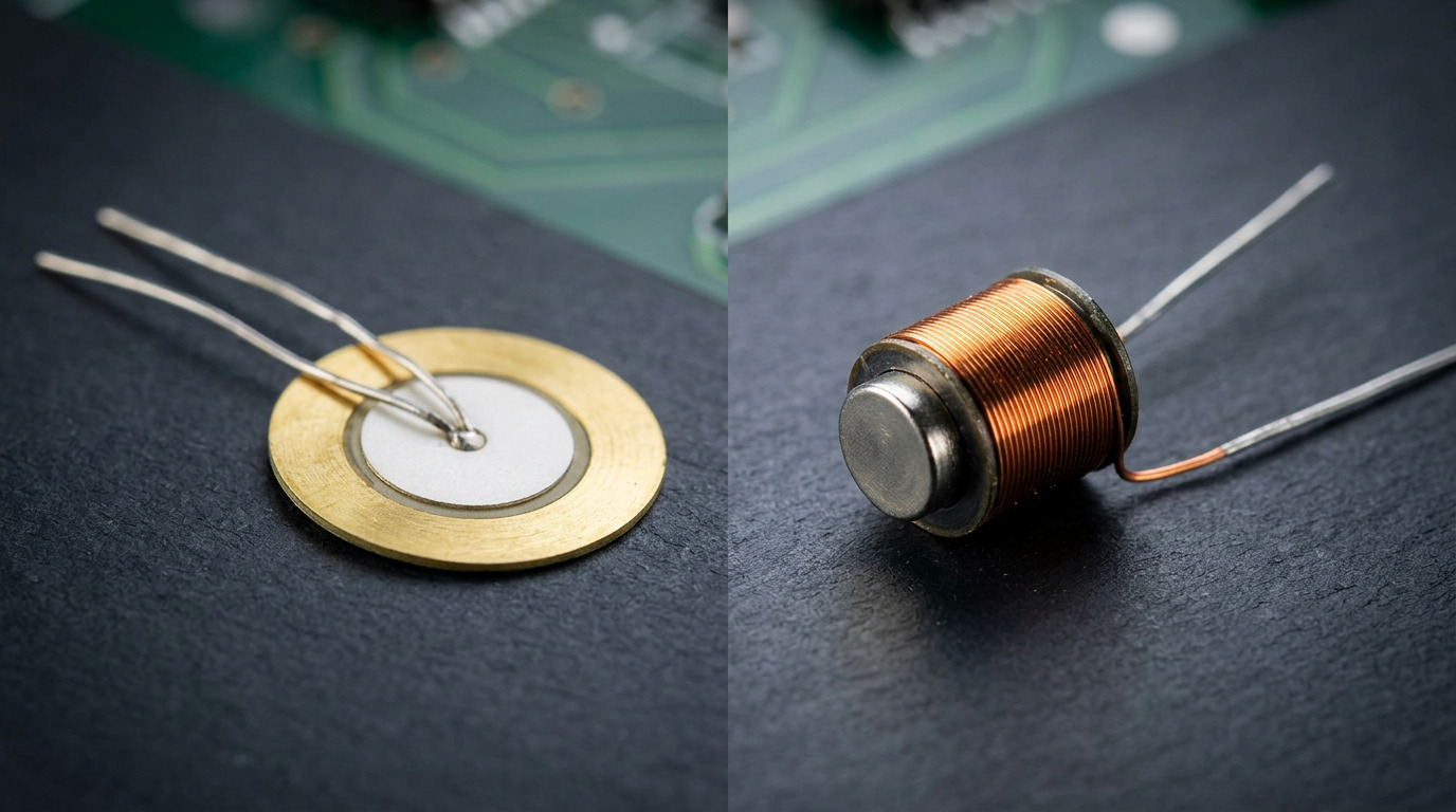
VDC means the part contains its own oscillator. Apply a steady voltage and it sounds. The BPC2310 (6 ~ 15 VDC) and the BMC1265-0527 (1 – 12 VDC) are both in this category. Your microcontroller needs one GPIO and, for anything above a few milliamps, one switching transistor.
Vp-p means the part is a bare acoustic element. It has no oscillator. Apply a steady voltage and you get a click, then silence. The BP1440-40 (1~25 Vp-p) and the BP1770C-0540 (1 – 30 Vp-p) are in this category. Your microcontroller must generate a continuous square wave, which means a hardware timer, a PWM channel, and firmware that keeps that channel running for as long as the alert needs to sound.
Two consequences follow directly from the unit on that line. First, a 30 Vp-p rating on a passive part is an amplitude rating, not a voltage rail you can connect to — the element is driven differentially, so the swing across the two terminals is what matters. Second, the peak-to-peak convention is why passive parts appear to accept "higher voltages" than active ones. A passive part rated 1 – 30 Vp-p and an active part rated 6 ~ 15 VDC are not in conflict; they are describing different quantities.
Both passive piezo sheets print a capacitance value, and neither is directly comparable to the other:
BP1440-40: 15000 ±30% pF @1KHz
BP1770C-0540: 15000 ± 30% pF at 120 Hz, 1 V
Same nominal figure, different test frequency. A piezo ceramic element is not a pure capacitor; its impedance varies with frequency, so a capacitance reading taken at 120 Hz and one taken at 1 kHz describe the element at two different points on the same curve. If you are dimensioning a series resistor or calculating drive current, use the value at the frequency you intend to drive, or better, work from the impedance at your operating frequency rather than from a single low-frequency capacitance number.
The tolerance is worth noting too: ±30% on both. That is a wide spread, and it propagates directly into turn-on transients. Two units from the same batch can present noticeably different inrush behaviour when first driven, which is one reason a small series resistor between the driver and a passive piezo is common practice even when the schematic does not appear to need one.
Operating and storage temperature are printed separately on every one of these sheets, and they are not interchangeable:
Model | Operating | Storage |
|---|---|---|
BPC2310 |
|
|
BP1440-40 |
|
|
The storage window is wider on both ends. That is normal and it means something specific: the part can survive being shipped and warehoused outside its operating band, but it is not characterised for acoustic output there. If your product sits in an unheated container in winter and is then powered on immediately, the first few minutes of operation are outside the operating band even though the part is undamaged.
For a passive piezo, temperature also shifts the resonant frequency, because the mechanical stiffness of the ceramic and the mounting structure change with temperature. A part specified at 4000 ±500 Hz at room temperature will not hold that band across a −20 to +70 ℃ operating range. If the tone must stay on pitch in a cold-start scenario, the tolerance line and the temperature line have to be read together, not separately.
The last block on the sheet is the one that stops a design at the layout stage rather than at the prototype stage. Three separate things hide here: the acoustic aperture, the footprint, and the pin geometry.
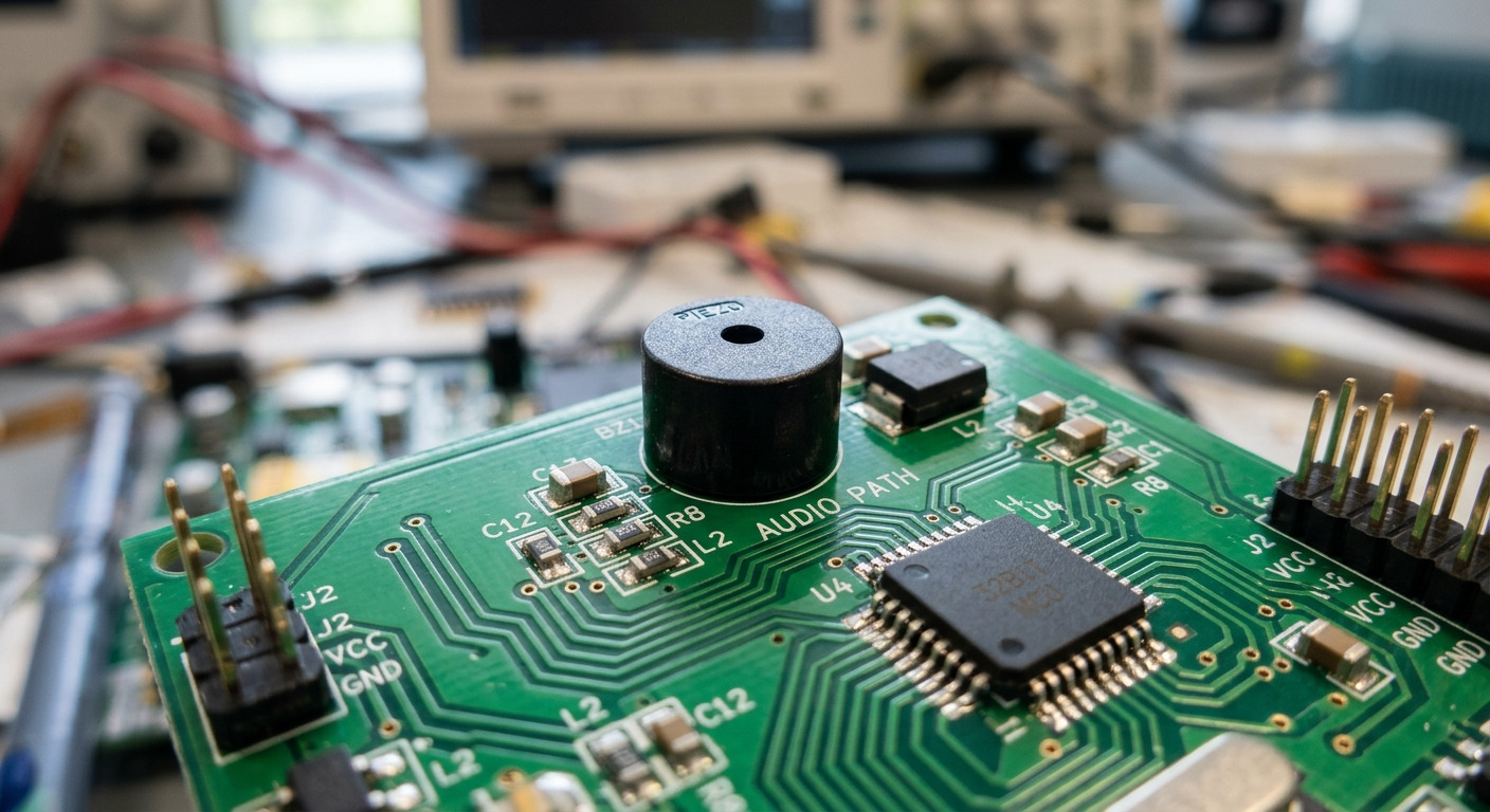
Take the BMC1265-0527. Its sheet states Φ12 mm body diameter, 6.5 mm body height, Potted seal, center emission hole, and DIP through-hole pins; 2 * Φ0.6 mm; spacing 7.6 mm; pin extension 5 mm. That single line settles four layout questions: hole diameter, hole spacing, the keep-out under the board for the pin tails, and where the sound escapes. If the emission hole faces the PCB rather than away from it, the enclosure design has to provide a path for the sound, and no amount of electrical correctness will fix a part that is acoustically sealed against the board.
The BP1770C-0540 sheet is more compact but equally load-bearing: Φ17 ± 0.5 * 7 ± 0.3 mm, Through-hole pins, 10.5 mm pin spacing, Pin Length 3.1 ± 0.5 mm. The ±0.5 mm on the diameter is a fit tolerance for the housing cutout, not a manufacturing nicety. A panel or enclosure opening designed to the nominal 17 mm without the tolerance will bind on the upper end of the distribution.
No single line on a buzzer datasheet is sufficient, and this is the point that separates an acoustic component from a passive one. The eight lines form a set of conditions that must be satisfied simultaneously:
Line | What it literally states | What it actually governs |
|---|---|---|
Rated voltage | Characterisation reference | Which of the other figures apply |
Operating voltage | Usable supply window | Whether the part functions at your rail |
Rated current | Draw at a stated condition | Battery and regulator budget |
SPL | Output at a stated distance and drive | Audibility in the enclosure |
Resonant frequency | Peak with tolerance | Tone stability across production |
Drive signal format | VDC or Vp-p | Whether you need a timer and PWM |
Capacitance | Element value at a test frequency | Drive current and transient behaviour |
Dimensions and mounting | Geometry and aperture | Whether it fits and whether it is heard |
A specification review that checks these lines one at a time will pass parts that fail in the enclosure. A review that checks them as a set — rail inside the operating window, drive format matched to the circuit, SPL quoted at a distance the enclosure can actually deliver, frequency tolerance compatible with the firmware's fixed tone — is the review that catches the problem before tooling.
Three errors account for most of the field failures that trace back to a datasheet rather than to a design.
Comparing dB across parts with different drive conditions. As shown above, 90 dB @ 12 VDC and 85 dB @ 5 Vp-p are not on the same scale. Before any comparison, normalise the drive condition, or accept that the comparison is qualitative.
Treating the operating range as a performance guarantee. The range tells you the part still functions. It does not tell you the SPL, current, or frequency holds across that range. Every figure on the sheet is anchored to the rated point.
Reading a tolerance as a manufacturing defect rate. A ±500 Hz band is the specification, not a quality problem. If the band is too wide for the application, the answer is a different architecture — an internally driven part, or end-of-line tuning — not a tighter incoming inspection.
A buzzer datasheet is short because the component is simple, not because the decision is. Each of the eight lines converts a physical behaviour into a number by fixing everything else — distance, drive voltage, waveform, duty cycle, test frequency, ambient temperature. Reading the sheet properly means reading those fixed conditions as part of the number, and then checking whether the conditions your circuit will actually impose match the conditions the manufacturer used.
The four parts referenced here span the two architectural families: internally driven indicators where the oscillator is inside the housing and the design task is largely mechanical, and externally driven transducers where the design task includes generating the drive signal and accepting the consequences for current, tone stability, and firmware overhead. Both families are legible on the same eight lines. The difference is which lines carry the risk.
A: Trust the structured parameter table, and treat any summary block above it as promotional shorthand. When the two disagree on a figure you intend to design around — frequency tolerance, capacitance, weight — ask the supplier to confirm in writing before you commit to a footprint or a firmware constant. Discrepancies of this kind usually mean the summary block was written earlier and not refreshed when the parameter table was updated.
A: The operating voltage line is the limit, not the rated voltage line, and duty cycle does not extend it. A part rated 12 VDC with an operating range of 6 ~ 15 VDC is characterised to 15 V. Running it at 24 V — even briefly — puts it outside every condition the sheet describes, and the failure mode for an internally driven piezo is usually the oscillator circuit rather than the acoustic element.
A: No, for two reasons. The dB figure is measured at a stated distance and drive condition, so a part measured at 12 V will usually beat a part measured at 5 V regardless of acoustic design. And the figure is measured in free air; once the part is inside your enclosure, the aperture, the cavity volume, and the distance from the port to the user dominate. A 90 dB part mounted behind a restricted grille can be quieter than an 85 dB part with a clear path.
A: It tells you the element's impedance at the stated test frequency, which is the starting point for calculating drive current and for choosing a series resistor. It does not tell you the acoustic output, and it is not constant across frequency. Because the test frequency differs between manufacturers — @1KHz on one sheet, at 120 Hz on another — two parts with the same printed capacitance are not necessarily equivalent loads at your operating frequency.


