
English 
Dedicated to global electroacoustic technology.
Views: 0 Author: Site Editor Publish Time: 2026-08-17 Origin: Site


Auditory feedback plays a crucial role in modern user interfaces and hardware design. However, engineers often overlook the nuances of selecting the correct audio component. Choosing the wrong part frequently causes unnecessary software overhead. It can also lead to bloated hardware costs or inadequate sound output. You must carefully evaluate your project requirements before finalizing a bill of materials.
The fundamental choice usually narrows down to an active or a passive component. This decision primarily balances implementation simplicity against audio flexibility. Each option demands a distinctly different approach to both hardware circuitry and software architecture. Making an informed choice early prevents costly revisions later in the development cycle.
This guide provides a clear, engineering-focused evaluation of both component types. You will learn about their working principles and examine their required driving circuits. We also offer a practical decision framework. Use this information to integrate the ideal auditory solution into your next prototype or production run.
Active Buzzers contain an internal oscillator. They require only a simple DC voltage to produce a single, fixed-frequency tone.
Passive Buzzers lack an internal oscillator. They require an external AC signal or PWM (Pulse Width Modulation) to generate sound, allowing for variable frequencies and complex melodies.
Identification Trick: Flipping the component over usually reveals a green PCB on passive variants, while active variants are typically sealed with black potting compound.
Implementation Reality: Microcontroller (MCU) GPIO pins rarely output enough current to drive either buzzer directly; a simple transistor switching circuit is almost always required.
Understanding how these components generate sound requires looking inside their external housing. The primary distinction lies in their internal circuitry. This single design choice dictates your entire hardware and software integration strategy.
The Internal Oscillator (The Defining Factor)
An internal oscillating circuit acts as the heartbeat of an audio component. It automatically rapidly switches voltage on and off. If this circuit is present, the component manages its own sound generation. You merely provide a steady power source. If this oscillator is absent, your microcontroller must take over the switching responsibility. This absence forces you to generate a precise oscillating signal using code.
Structural Mechanics (Piezoelectric vs. Magnetic)
Engineers often confuse signal generation methods and physical transducer mechanics. Both active and passive variants can utilize either piezoelectric or magnetic mechanisms to move their diaphragm. A piezoelectric unit uses a specially formulated ceramic crystal. This crystal deforms physically when exposed to an electrical field. A magnetic unit uses a wire coil and a magnet. Current passing through the coil creates an electromagnetic field. This field pulls a metal diaphragm downward. Releasing the current allows the diaphragm to snap back. The active or passive designation refers strictly to the signal generation method. It does not describe the physical sound transducer itself.
Signal Requirements
Because of their distinct internal structures, these devices demand entirely different input signals to operate correctly.
Active: Requires continuous DC power. You typically supply a constant 3.3V or 5V directly to the power pins.
Passive: Requires a square wave. You must supply an alternating current (AC) or a Pulse Width Modulation (PWM) signal. This signal must alternate between HIGH and LOW states. You generally use a frequency between 2kHz and 5kHz to produce an audible tone.
Component Characteristic Comparison
Feature | Active Type | Passive Type |
|---|---|---|
Internal Oscillator | Present | Absent |
Input Signal | Steady DC Voltage | PWM / Square Wave |
Audio Output | Single, fixed tone | Variable tones, melodies |
Software Overhead | Extremely Low | Moderate to High |
Visual Identifier | Black epoxy base | Exposed green PCB |
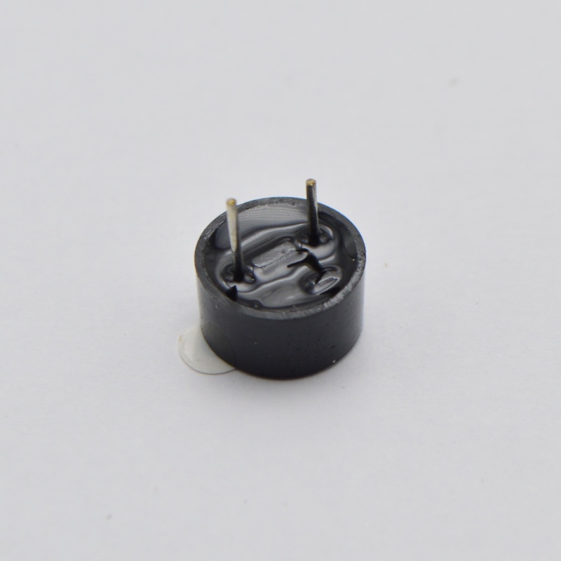
Hardware developers frequently prioritize speed and simplicity. An Active Buzzer excels in these areas. It offloads the complex timing tasks from your microcontroller.
Primary Advantage (Ease of Integration)
The greatest benefit of this component is its absolute simplicity. It requires zero CPU timer resources. You do not need to configure hardware PWM channels. A simple digital command turns it on. Setting a GPIO pin to HIGH produces immediate sound. Setting it to LOW stops the sound. This frees up your microcontroller to handle other critical operations.
Implementation Realities & Limitations
Convenience always comes at a cost. The built-in oscillator heavily restricts your audio options. You face several strict limitations.
It produces a single, monotonic beep. You cannot change the pitch or play a melody.
Volume control proves difficult. You cannot easily adjust the loudness via software. Controlling volume usually requires adjusting the physical supply voltage using external hardware.
The unit cost runs slightly higher. The internal oscillator circuitry adds additional components to the manufacturing process.
Ideal Use Cases
Despite these limitations, this component shines in specific scenarios. Use it for critical fault alarms where a loud, piercing noise is necessary. It works perfectly for basic power-on indicators. Simple status alerts, like a microwave oven signaling a finished cycle, represent ideal applications. It is also the best choice for projects where microcontroller timer pins remain scarce.
Modern user interfaces often demand nuanced auditory feedback. A Passive Buzzer provides the necessary acoustic range. It trades integration simplicity for extensive functional flexibility.
Primary Advantage (Audio Versatility)
This component can reproduce a wide range of frequencies. You control the pitch entirely through software. This allows your hardware to play distinct melodies. You can program multi-tone alerts to signify different system states. Dynamic UI feedback becomes possible. A rising tone might indicate success, while a falling tone indicates failure.
Implementation Realities & Risks
Achieving this versatility requires careful software engineering. You must manage several distinct risks during development.
It requires dedicated MCU timer blocks. You must use PWM-capable pins. Programming environments often provide specific functions for this, such as the `tone()` function in Arduino.
Software overhead increases significantly. You must generate continuous signal pulses. Using blocking code to manage these pulses can disrupt other critical timing loops. You must implement non-blocking timer interrupts for complex systems.
Sending an incorrect signal creates hardware stress. Failure to provide a varying signal results in no sound. Applying a flat DC voltage to the coil generates excessive heat. This common mistake causes potential component stress and early failure.
Ideal Use Cases
This component perfectly suits sophisticated electronics. Medical device user interfaces require distinct tones to differentiate between routine notifications and critical alarms. Consumer electronics rely on complex audio to enhance user experience. Toys heavily utilize variable frequencies to play music. Any system requiring nuanced auditory feedback mandates this passive approach.
A common beginner mistake involves powering an audio component directly from a microcontroller GPIO pin. You must understand electrical current limits to prevent catastrophic hardware damage.
The Direct-Drive Risk
Microcontroller pins have strict current limits. A typical pin might safely supply a maximum of 20mA. Audio components often draw 30mA, 50mA, or even 100mA during operation. Drawing excess current through a GPIO pin burns out the internal silicon. You risk permanent MCU damage. You must use a dedicated driver circuit to separate the control signal from the power delivery.
A simple transistor switch solves the current limitation problem. The microcontroller supplies a tiny control current. The transistor handles the heavy power delivery. Here are the core components of a standard low-side switch.
NPN Transistor: Components like the 2N2222 or BC547 work exceptionally well. You use the transistor as a switch on the low side. You connect the component's negative pin to the transistor collector. You connect the transistor emitter directly to ground.
Base Resistor: You must place a resistor between the MCU pin and the transistor base. This is essential for limiting current. A value between 1kΩ and 4.7kΩ typically works best. It prevents the transistor base from drawing too much current from the MCU.
Power Source: Connect the component's positive pin directly to your main power rail. This might be a 5V or 12V supply, depending on the component's rating.
Magnetic audio components contain internal wire coils. These coils act as inductors. They store energy in a magnetic field while powered. When you turn the transistor off, the magnetic field collapses rapidly. This collapse generates a massive reverse voltage spike. We call this phenomenon inductive kickback.
Flyback Diode Requirement
You must place a flyback diode in parallel with a magnetic component. Ensure you orient the diode backwards relative to standard current flow. Connect the cathode to the positive supply and the anode to the transistor collector. When the voltage spikes, the diode provides a safe path for the current to loop back. This protects your fragile transistor from destruction.
Credibility Check: Piezoelectric Considerations
Piezoelectric variants lack wire coils. They generally behave like capacitors rather than inductors. They do not generate massive reverse voltage spikes. Consequently, they do not explicitly require flyback diodes. However, including a flyback diode in your universal driver circuit remains standard defensive engineering practice. It prevents failures if someone accidentally swaps a piezo unit for a magnetic one later.
Selecting the perfect Buzzer requires analyzing your system architecture. You must balance hardware limits against user experience goals. Follow this framework to make the best engineering choice.
Evaluate MCU Resource Availability
First, audit your microcontroller resources. Check how many hardware timers remain available. Look at your PWM channel usage. If your design already maxes out these resources for motor control or LED dimming, you lack the bandwidth to generate audio pulses. In this scenario, you must default to an active variant. It requires only a standard digital pin.
Define Success Criteria for Auditory Feedback
Determine exactly what the user needs to hear. Differentiate between a simple alarm and complex interaction feedback.
Alarm vs. Interaction: If the user just needs to know a basic "System Fault" occurred, an active unit proves sufficient. Its loud, fixed tone effectively grabs attention. If the user needs to differentiate between "Success," "Warning," and "Critical Error," a passive unit becomes mandatory. The ability to play distinct melodies provides superior user context.
BOM Cost vs. Software Development
Evaluate your project budget and development timeline. Passive components usually cost marginally less on the raw bill of materials. However, they require significantly more software development and testing time. Writing non-blocking audio code consumes engineering hours. Active components cost slightly more per unit but drastically offload complexity to the hardware. Choose based on whether your constraint is unit price or developer time.
Scalability & Footprint
Both types come in various physical packages. You can find through-hole options for wave soldering and SMD (Surface Mount Device) packages for automated pick-and-place assembly. Physical footprint rarely dictates the final choice. However, operating voltage matters immensely. Ensure the component's rated voltage (usually 3V, 5V, or 12V) aligns perfectly with your existing power rail. Introducing a new voltage regulator solely for audio feedback ruins design efficiency.
Navigating auditory feedback requires a solid grasp of basic electronics. Neither component is universally superior. Active units win clearly on deployment speed and overall hardware simplicity. They remain the go-to choice for basic alarms. Passive units win decisively on functional flexibility and acoustic range. They enable the rich, nuanced feedback required by modern interactive devices.
Your next steps involve closely reviewing your project's hardware schematic. Audit your microcontroller pinout to verify available timer resources. Assess your software architecture to see if non-blocking audio generation fits your processing loops.
Before finalizing your design, evaluate your specific voltage requirements. Ensure your chosen transistor driver circuit can handle the component's maximum current draw. Review technical datasheets and supplier catalogs to secure high-quality audio components that meet your exact specifications.
A: You are likely sending it a flat DC signal. Setting a digital pin strictly to HIGH only energizes the internal coil once, resulting in a single physical click. You must send a repeating square wave or PWM signal to rapidly oscillate the diaphragm and produce an audible tone.
A: Not easily via code. Because it relies on an internal oscillator powered by DC, you cannot alter a duty cycle to lower the sound. You must limit the current using a series resistor or lower the physical supply voltage to reduce the volume output.
A: Look at the bottom pins. A passive unit typically exposes a green circuit board. An active unit is generally sealed with black epoxy to protect its internal oscillator. You can also test with a multimeter. Passive units usually show a specific coil resistance value, while active ones do not.


