
English 
Dedicated to global electroacoustic technology.
Views: 0 Author: Site Editor Publish Time: 2026-11-16 Origin: Site


Most buzzer design questions start in the same place: someone has a spare GPIO or a 12 V rail, a part on the bench, and a deadline. For an active piezo the answer is usually shorter than expected, because the hardest part of the circuit is already inside the can. But "shorter" is not "nothing", and the handful of details that remain are the ones that decide whether the indicator sounds clean for five years or fails a field return in month three.
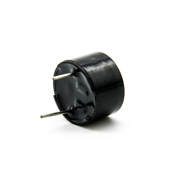
This article walks through what an active piezo buzzer removes from a board, what it still requires, and how to confirm the result without a lab full of instruments. The reference part throughout is the TAT BPC1475-1240, a 12 VDC active piezo in a Φ13.8 × H7.5 mm pin-mount package.
A passive piezo is a ceramic disc and nothing else. It needs an alternating drive at something close to its resonant frequency, which means your firmware has to produce a square wave on a timer channel, and your board has to carry a switching device to swing the voltage high enough. That is a real circuit: a transistor, a base or gate resistor, often a flyback path, and a pin that must stay dedicated for as long as the product ships.
An active piezo carries its own oscillating circuit inside the housing. Apply DC and it sounds. There is no timer to configure, no frequency to tune, and no switching device between the supply and the part. The firmware work reduces to setting a pin high, and the bill of materials reduces to the buzzer plus whatever decoupling the rest of the board already has.
That is the entire value proposition, and it is worth stating precisely: an active part converts a firmware and analogue design task into a power switching task. Nothing more, nothing less.
Convenience has a cost, and on an active part the cost is control.
The internal oscillator fixes the tone. The BPC1475-1240 runs at a resonant frequency of 4000±500 Hz with a continuous tone, and there is no pin to change it. If a product needs a pulsed pattern, a two-tone alarm or a chime, the pattern has to come from switching the supply on and off rather than from shaping a waveform. That is entirely workable, but it changes what the firmware has to do, and it changes the current profile as well.
The oscillator also draws current. A part rated at a maximum of 10 mA at 12 VDC is spending part of that budget on its own drive circuit rather than on acoustic output. This is the honest way to compare an active part against a passive one: not "which draws less", but "which spends its current more usefully for this product". A passive part pushes the drive cost onto your transistor; an active part folds it into the can.
There is a third consequence that catches people later. Because the oscillator is a circuit, it has a start-up behaviour. An active piezo does not necessarily reach full output in the first millisecond, and if a product's specification says the alarm must be audible within a defined window after power-up, that window should be measured rather than assumed.
The circuit is short enough to describe in a paragraph, which is exactly why the details matter.
Connect the positive pin to the switched supply and the negative pin to ground, observing the polarity markings on the terminal. The BPC1475-1240 uses pin terminals with polarity identification, and the pin dimensions are L1 = 4.0±0.5 mm, L2 = 5.5±0.5 mm with Φ = 0.6±0.1 mm, so it drops into a standard through-hole footprint without a custom stencil.
Switch the supply with whatever device matches the rail. On a 12 VDC rail driven from a microcontroller, that is usually a small N-channel MOSFET or a bipolar transistor with the emitter to ground, because the buzzer's return path is the low side. A high-side switch works equally well and keeps the buzzer's negative terminal at ground, which some layouts prefer.
Keep the switching device rated for the inrush rather than the steady figure. A piezo is a capacitor, so the first moments after switch-on look like a charging event, and a device selected only against the 10 mA maximum has no margin for that transient.
Decouple locally. The part is rated for an operating voltage range of 3 to 16 VDC, which means it will keep working across a wide spread of supply conditions, but a long trace back to a shared regulator can still impose a dip at switch-on that other circuits on the board will notice.
Designers often ask whether a resistor is needed in series with an active piezo. The honest answer is: not for the buzzer's sake, but sometimes for the board's.
A series resistor does not protect an active piezo the way a base resistor protects a transistor. What it can do is limit the charging current at switch-on, soften the acoustic attack, or trim the output level when a fixed-tone part is louder than the application needs. On a part that delivers a minimum of 85 dB at 10 cm, an application in a quiet enclosure may well want less than full output, and a resistor is the cheapest way to get there.
The trade is that any series resistance also drops voltage across itself. With an operating range of 3 to 16 VDC, a 12 VDC nominal rail has room to spare, which is what makes the resistor practical on this part in the first place. On a rail already near the bottom of the range, the same resistor would eat the margin and change the tone.
Never use a series resistor as a substitute for a proper switch. A GPIO pin is not a power source for a continuous milliampere load, and a resistor between the pin and the buzzer simply converts the problem into heat and a quiet indicator.
A specification table is a compressed document, and the compression hides conditions. Three habits make it readable.
First, separate rated from operating. The rated voltage is the condition at which the acoustic and current figures were produced; the operating range is what the part survives. The BPC1475-1240 is rated at 12 VDC and operates from 3 to 16 VDC. Running it at 5 VDC is legitimate and will produce a quieter tone than the rated figure; the 85 dB number does not transfer to that condition.
Second, read the word "maximum" as a design bound. A current figure stated as a maximum covers the production spread and the stated test condition. Size the supply for it, then verify the typical on a sample.
Third, check whether the acoustic figure has a distance attached. Ours are stated at 10 cm, so comparisons across suppliers only hold when the other figure was taken at the same distance with instrumentation conforming to the sound level meter requirements of IEC 61672-1. A number without a distance is not comparable to anything.
Where the finished product is a medical device, the audible alarm behaviour of the system is addressed by IEC 60601-1-8. That is a system-level requirement rather than a buzzer property, and the edition in force governs; we point readers to the published text rather than summarising it here.
The temperature range belongs in the same reading. The BPC1475-1240 is rated for -40℃ to +90℃ in both operation and storage, and the black PBT housing is potted for stability and moisture resistance. Those are housing and construction statements. They are not a claim about performance in a washdown or an outdoor enclosure, and any product that needs that behaviour should be qualified as a system.
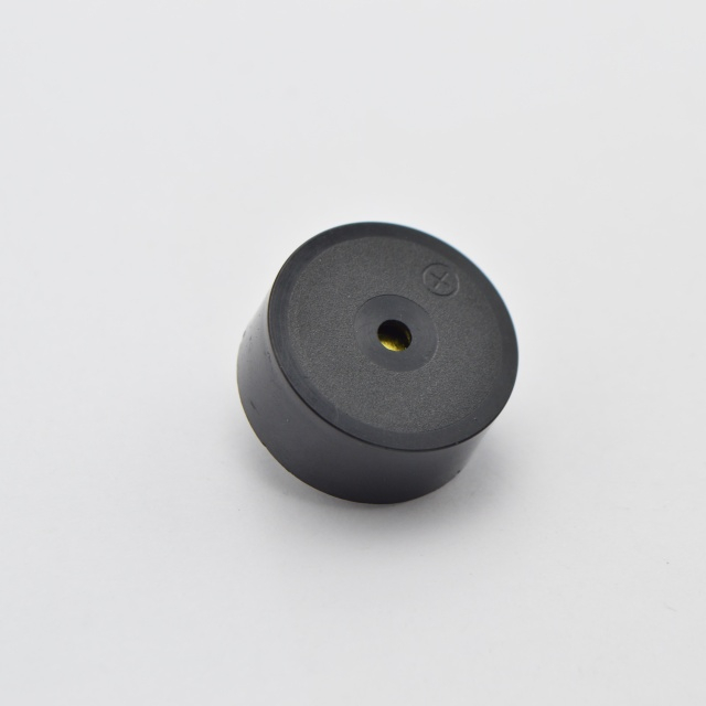
The BPC1475-1240 and the BPC2310 are both 12 VDC active piezos, and the differences are the ones that decide a design.
The BPC1475-1240 is the smaller package at Φ13.8 × H7.5 mm, delivers a minimum of 85 dB at 10 cm, runs at 4000±500 Hz, draws a maximum of 10 mA at 12 VDC, and covers -40℃ to +90℃. Its 3 to 16 VDC operating range makes it comfortable on a 12 V rail with tolerance and on a 5 V rail at reduced output.
The BPC2310 is the 23 mm class part, delivers a minimum of 90 dB at 10 cm, runs at 3500±500 Hz, draws a maximum of 15 mA at 12 VDC, and covers -20℃ to +70℃ with a 6 to 15 VDC operating range.
So the choice is roughly five decibels against five milliamps and thirty degrees of temperature headroom. If the product lives indoors and the enclosure is quiet, the smaller part is usually enough. If the indicator has to cut through machinery noise, the larger part earns its current. If the product ships to a cold store or sits near a heat source, the wider temperature range decides the question before acoustics do.
A bench check does not need a chamber, but it does need to be repeatable.
Measure sound output at a fixed 10 cm with the same meter and the same orientation each time, and note the meter's weighting setting so the next person can reproduce the result. Compare against the catalogue minimum rather than a remembered number.
Measure current with the part sounding continuously, at the rated voltage, and again at the bottom of the operating range. The two readings describe different products, and both are useful.
Check the switch-on transient with a scope across the supply pins. A dip that lasts a few microseconds is normal; a dip that disturbs a neighbouring analogue channel is a layout problem, and it will show up here rather than in the field.
Finally, listen. A piezo that sounds harsh or intermittent on the bench is not going to improve in an enclosure. The whole point of an active part is that the acoustic result is fixed by the can, so if the can is wrong, no amount of firmware will rescue it.
Choosing an active piezo buzzer is mostly a matter of accepting a trade rather than solving a circuit. You give up control of the tone and of the current profile, and in exchange you remove a timer, a switching stage and a tuning exercise from the design.
The BPC1475-1240 sits at the simple end of that trade: a 12 VDC part with a 3 to 16 VDC operating range, a maximum of 10 mA at 12 VDC, a minimum of 85 dB at 10 cm, and a temperature range wide enough that most indoor and industrial cabinets never touch its limits. Wire it to a switch, decouple it locally, confirm the transient on a scope, and the audible indicator stops being a design task.
Our active and passive buzzer range lists the operating voltage, current, frequency and test distance for each part, so the comparison above can be repeated for any model in the catalogue.
Not for continuous operation. An active part drawing a maximum of 10 mA at 12 VDC needs a switching device rated for that current plus the switch-on transient. A GPIO pin can control the switch, but it should not carry the load.
Usually not for protection. A series resistor is a way to trim output level or soften the charging transient, and it is practical on this part because the 3 to 16 VDC operating range leaves margin above the 12 VDC rating. It is not a substitute for a proper switch.
Because the acoustic figures are produced at the rated voltage. The BPC1475-1240 is rated at 12 VDC, and its minimum of 85 dB at 10 cm belongs to that condition. At 5 VDC the part still works inside its operating range, but the output is lower and the current draw changes too.
Not internally. The 4000±500 Hz tone of this part comes from its built-in oscillating circuit, and there is no external pin to retune it. Patterns such as pulsed or intermittent tones come from switching the supply, which is a firmware decision rather than a component one.
The potting improves stability and moisture resistance, and the housing is black PBT rated across a wide temperature range. That is not the same as an outdoor or washdown rating for a finished product, and an application that needs one should qualify the assembled unit rather than rely on the buzzer alone.
Compare total system current and total board area, not just the buzzer line. A passive part shifts the drive circuit onto your board, which adds a switching device and a firmware task; an active part folds that cost into the can. For a fixed 12 VDC rail and no tuning requirement, the active route is usually the shorter path.


