
English 
Dedicated to global electroacoustic technology.
Views: 0 Author: Site Editor Publish Time: 2026-11-15 Origin: Site


Most buzzer discussions start with sound. This one starts with the parts you no longer have to place. A self-drive buzzer carries its own oscillator, so the decision to use one is really a decision about the bill of materials: what disappears from the board, what the firmware no longer has to generate, and what the test plan no longer has to calibrate.
The TAT BMC1295 is a useful reference point for that arithmetic, because its published envelope is deliberately wide: DC operation from 1.5 to 12 V, 20 to 50 mA of current, 85 to 95 dB at 10 cm, and frequency held within ±2 to 3 percent. Wide envelopes are what let one part cover a product family, and they are also what makes the integration questions worth asking properly.
A passive piezo or magnetic transducer is a component that needs a partner. Something has to produce the alternating waveform, and that something is either a dedicated oscillator IC, a transistor pair driving a tuned network, or a timer channel inside the microcontroller running at exactly the right frequency. Each of those options costs a line on the BOM, a line in the pick-and-place program, and a line in the test procedure.
A self-drive part collapses that into one line. The BMC1295 contains a coil-driven metallic diaphragm and the circuit that alternates the field around it, so the electrical interface reduces to a DC source and a switch. The saving is rarely the cost of the removed parts; it is the engineering time that no longer goes into tuning them, and the production variance that no longer exists once there is nothing left to tune.
There is a second, quieter saving. Every passive design carries a frequency tolerance that belongs to the external network as much as to the component, which means two boards built to the same drawing can sound slightly different. With the oscillator inside the housing, the tolerance travels with the part, and the tone becomes a purchased specification rather than a manufactured outcome.
The 1.5 to 12 V window is the reason this family fits so many products. The same part can sit on a 3 V logic rail, a 5 V USB-derived rail, or a 12 V rail inherited from a relay circuit, without a regulator of its own. When you are consolidating a platform across several appliance models, that flexibility is worth more than a narrow, optimised part number.
Current draw of 20 to 50 mA is the other half of the budget. It is modest enough that a small regulator will not notice it, and large enough that you should still check it against the rail's worst case rather than its typical case. A buzzer is an intermittent load, so the honest calculation is the average over the duty cycle plus the peak during the tone, not the quiescent figure alone.
Two rail details deserve attention before layout. First, the buzzer's return current should not share a thin trace with an analogue reference; even a modest current switching on and off will show up as a step. Second, if the rail is also feeding a relay or a motor driver, the buzzer will hear the supply sag, and the tone will follow it. Neither problem needs a special part, only a route that keeps the switching loop local.
With a self-drive part, the firmware contract is a single digital output. High means sound, low means silence. There is no frequency to configure, no duty cycle to hold, and no timer resource to reserve. That last point is easy to underestimate: on a small microcontroller already generating a PWM for a backlight and a carrier for an IR link, a third timer channel is sometimes the part of the design that forces a larger device.
The trade-off is that the tone is fixed. If the product needs two distinct alerts, the usual answer is two parts, or a part with a switching input, not a clever firmware trick. Deciding this early matters, because "we will change the pitch in software" is the assumption that most often survives the schematic review and fails at the first customer complaint.
One practical note on the interface: drive the buzzer from a transistor or a dedicated output stage rather than directly from a GPIO pin whenever the current budget is close to the pin's rating. The 20 to 50 mA envelope is within reach of many modern pins, but a pin that is asked to source its maximum while also driving a capacitive load is a pin that will be derated in the next revision.
The 85 to 95 dB specification is quoted at 10 cm, and that distance is not a formality. Sound pressure falls with distance, and it falls differently indoors where reflections add to the direct path. A number measured at 10 cm tells you about the source; it does not tell you what an operator hears two metres away across a running appliance.
This is why the measurement standard matters as much as the number. Sound level meters are specified separately from the products they measure, under IEC 61672-1, which is where the instrument classes and their tolerances are defined. If a supplier quotes a level without saying which instrument class produced it, the figure is a conversation starter rather than a specification. Our own note on what a dB figure at 10 cm actually measures goes through the same point in more detail.
The 85 to 95 dB spread also has a practical reading. It is a range across the family, not a tolerance on one unit, which means the part you qualify at the quiet end is not interchangeable with the part at the loud end without a listening check. When an appliance has to be audible over a wash cycle, specify the end of the range you actually need, then verify it on the assembled unit.
A tolerance of ±2 to 3 percent sounds unremarkable until you compare it with what a passive design can drift to. In a passive circuit, the tone depends on the drive frequency, the element's resonance, and the tolerance of every passive around them. In a self-drive part, the same tolerance is a property of the sealed assembly, and it does not move when the board is re-spun.
Where this shows up is in product families. A platform that ships in four variants with the same alert tone needs the tone to be the same in all four, and "the same" has to survive a change of supplier for the surrounding components. A part whose frequency is fixed inside the housing makes that requirement easy to write into a drawing and easy to check on an incoming inspection bench.
There is a limit worth stating plainly. Stability is not the same as accuracy against a target pitch, and neither is the same as loudness. A part can hold its frequency perfectly and still be too quiet for the application, which is why the two numbers have to be read together rather than ranked.
Self-drive is the default for indicator duty, not for every acoustic job. It stops being the right answer in three situations.
When the product needs a melody, a multi-tone pattern, or a warning that changes with severity, the fixed tone becomes a constraint rather than a simplification. When the acoustic design needs a specific resonance to match an enclosure, a passive element gives the designer a lever that a sealed oscillator does not. And when the alert has to meet an external signalling requirement — medical equipment is the clearest case, where alarm signal design is governed separately under IEC 60601-1-8 — the choice of drive architecture follows the requirement rather than the BOM.
For everything else, the comparison usually comes down to board space and firmware attention, and that is where the self-drive case is strongest. Our guide to active versus passive buzzer circuits sets out the same trade-off from the circuit side.
A self-drive magnetic buzzer is a mechanical part as much as an electrical one. The diaphragm has to move air, so the housing needs an acoustic path that is not blocked by a gasket, a label, or a cable loom pressed against the sound aperture. In a compact appliance the easiest place to lose several decibels is directly in front of the opening.
The mounting method matters for the same reason. A part held against a panel transmits vibration into the panel, and a panel that resonates will colour the tone in a way no datasheet captures. Standoffs, a soft washer, or a moulded seat that leaves the aperture clear are cheap insurance, and they are far easier to add at the drawing stage than after a noise complaint.
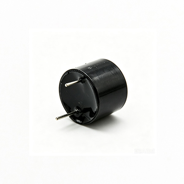
Nothing about the BMC1295's envelope forces a complicated installation: it is a compact cased part with two solder pins, intended to sit directly on the control board. The integration work is therefore mostly about the two things the datasheet cannot specify for you — where the sound escapes, and what the board looks like underneath it.
The case for a self-drive buzzer is not that it sounds better. It is that it removes a circuit, a tolerance, and a firmware dependency from the design, and replaces them with a purchased specification: 1.5 to 12 V DC in, 20 to 50 mA drawn, 85 to 95 dB at 10 cm out, held within ±2 to 3 percent.
That trade is worth making whenever the product needs one unmistakable tone and nothing more. It is worth questioning the moment the product needs a pattern, a tuned resonance, or compliance with a signalling standard. Either way, the decision belongs on the BOM review rather than in the acoustic lab, because by the time the first prototype sounds wrong, the parts you removed are no longer the problem.
Electrically it can, because the interface is a DC level, but the current envelope of 20 to 50 mA is close enough to many pin ratings that a buffer transistor is the safer default. Check the pin's absolute maximum against the buzzer's worst-case draw, not its typical draw.
Ten centimetres is a fixed reference that removes the room from the measurement. It says nothing about how loud the alert is across a kitchen, which is why the assembled product still needs its own listening test at the real distance.
It means the tone is repeatable. Accuracy against a target pitch is a separate specification, and loudness is a third. Read all three before you compare two parts.
The tone follows the rail. On a shared rail with a relay or a motor driver, keep the buzzer's switching loop local and give it a return path that does not run through an analogue reference, or the sag will be audible.
Cheaper on the BOM, usually, because it removes an oscillator and its passives. Not always cheaper overall: a product that needs several distinct tones may end up with two parts and a more complex assembly, which is the case where the passive route still wins. If you are weighing a specific part against a sibling, the BMC9650S-0527 shows how a narrower voltage window changes the same calculation.


