
English 
Dedicated to global electroacoustic technology.
Views: 0 Author: Site Editor Publish Time: 2026-11-10 Origin: Site


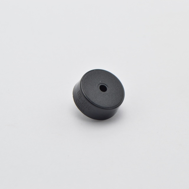
When evaluating acoustic components for electronic devices, the baseline metric that engineers rely upon is the buzzer sound pressure level at 10cm. But what exactly does this specification entail, and why is the ten-centimeter mark considered the industry standard for component-level acoustic testing? To fully grasp this, we must first delve into the physical principles that govern how acoustic energy is generated and measured.
Sound pressure level (SPL) is a logarithmic measure of the effective pressure of a sound relative to a reference value, typically expressed in decibels (dB). In the realm of small electronic acoustic components, the sound pressure level at 10cm represents the acoustic intensity captured at a precise distance of ten centimeters from the sound-emitting aperture of the component, situated on a central axis. This specific distance is chosen because it is far enough to avoid the extreme near-field acoustic anomalies where pressure waves are not yet fully formed, yet close enough to capture a strong, distinct signal without requiring massive acoustic power.
The generation of this acoustic pressure depends heavily on the underlying technology: magnetic or piezoelectric. In a magnetic architecture, an electromagnetic coil drives a metal diaphragm. When an alternating current passes through the coil, it creates a fluctuating magnetic field that interacts with a permanent magnet, forcing the diaphragm to oscillate and displace air. In a piezoelectric architecture, a ceramic disc bonded to a metal plate expands and contracts when subjected to an alternating voltage. This mechanical deformation pushes the surrounding air, generating sound waves. The efficiency of this energy conversion—and consequently the resulting buzzer sound pressure level at 10cm—is strictly tied to the driving frequency aligning with the mechanical resonant frequency of the component. When driven at resonance, the displacement of the diaphragm is maximized, resulting in the highest possible acoustic output.
From an OEM manufacturing perspective, the structural design is the primary differentiator in achieving a targeted sound pressure level. The physical breakdown of these components reveals a complex interplay of materials, cavity dimensions, and sound hole geometries. The resonant cavity, typically integrated into the plastic housing, acts as an acoustic amplifier. According to the Helmholtz resonance principle, the volume of the cavity and the diameter of the emission hole determine the frequency at which the system naturally amplifies sound.
OEM manufacturers must carefully control the injection molding tolerances of the housing to ensure consistency. A microscopic deviation in the thickness of the piezoelectric ceramic, or the tension of the metallic diaphragm in a magnetic variant, can drastically shift the resonant frequency and degrade the buzzer sound pressure level at 10cm. Furthermore, the mounting method—whether surface mount device (SMD), through-hole, or wire leads—affects the acoustic coupling with the printed circuit board (PCB). The PCB itself can inadvertently act as a secondary sounding board or a dampener, depending on the structural rigidity and the presence of acoustic isolation techniques.
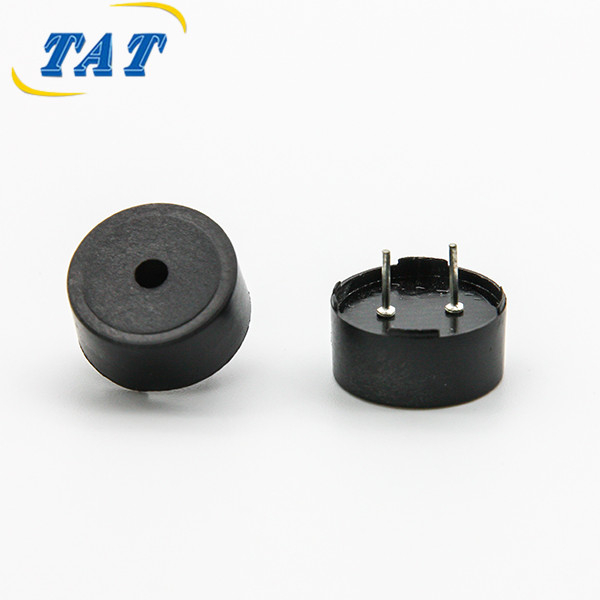
To ensure that the numbers printed on a datasheet are accurate and reproducible, acoustic testing must be conducted under strictly controlled laboratory conditions. The acoustic environment, driving circuitry, and measurement apparatus must all conform to standardized protocols to yield a valid buzzer sound pressure level at 10cm.
The cornerstone of acoustic measurement is the anechoic chamber. This specialized room is lined with wedge-shaped acoustic absorbers that prevent sound wave reflections, simulating an infinite free-field environment. Inside this chamber, the component is mounted on a standardized test baffle or PCB. A calibrated measurement microphone is positioned precisely 10 centimeters from the sound emission hole, directly on the primary acoustic axis.
The electrical parameters are just as critical as the physical environment. The operating voltage must be strictly regulated, as SPL is highly dependent on the input power. For instance, testing a component designed for a 5V system at 3V will result in a significantly lower decibel reading. Current consumption and the nature of the driving signal—typically a 50% duty cycle square wave for maximum harmonic richness and acoustic output—are continuously monitored. Temperature and humidity within the lab are also controlled, as air density and moisture can marginally affect sound propagation and the mechanical properties of the vibrating diaphragm. The procedures often align with international acoustic measurement protocols. For comprehensive guidelines on sound system equipment and measurement environments, engineers often refer to the IEC 60268 standards for sound system equipment.
Analyzing lab data reveals how different architectural choices influence performance. For example, when comparing components from a premier Buzzer Manufacturer, such as those found in the pl07 category, we can observe distinct acoustic profiles. Let us examine high sound pressure type models like the BM9055 and the BPC3020-1230.
The BM9055, often utilized in applications requiring a piercing, unmistakable alarm, is engineered to maximize the buzzer sound pressure level at 10cm by leveraging a highly optimized resonant cavity. Its frequency response curve typically shows a sharp peak at its rated resonant frequency, meaning it is incredibly efficient at converting electrical energy into acoustic energy at that specific pitch. Conversely, a model like the BPC3020-1230 might feature a slightly broader frequency response, sacrificing a few decibels of peak SPL in exchange for a less grating, more multi-tonal sound signature suitable for user interfaces. By analyzing the Fast Fourier Transform (FFT) data of these models, engineers can see not just the fundamental frequency, but the harmonic distortion profile, which determines whether the sound is perceived as a clean tone or a harsh buzz.
While a laboratory-measured buzzer sound pressure level at 10cm provides a necessary baseline for comparison, it is notorious for misleading inexperienced design engineers. The number on the datasheet represents an idealized scenario—a component operating in free air, driven perfectly at resonance, measured in a reflection-free room. Reality is rarely so accommodating.
One of the main reasons datasheet numbers fail to translate into real-world performance is the physical integration of the component into the final product. Once a component is placed inside a plastic or metal enclosure, the acoustic dynamics change completely. The enclosure acts as a low-pass filter, attenuating high-frequency sound waves. The sound must travel through the internal air volume, navigate around batteries and PCBs, and finally exit through whatever speaker grilles or acoustic vents are designed into the chassis.
This brings us to the complex calculation of cost versus performance trade-offs. An engineer might specify an extremely loud, high-cost component boasting a 95dB buzzer sound pressure level at 10cm, hoping that enough sound will escape the heavily sealed enclosure of a waterproof device. Alternatively, they could choose a lower-cost, 85dB component but invest engineering time into designing a custom acoustic wave-guide within the injection-molded housing to efficiently channel the sound to the exterior without attenuation. Balancing the bill of materials (BOM) cost with reliability and acoustic efficiency requires a deep understanding of mechanical acoustics, not just electrical specifications. Furthermore, driving circuits designed to save cost—such as using a simple microcontroller pin instead of a dedicated transistor or driver IC—may fail to provide the necessary current, resulting in an anemic acoustic output that falls far short of the datasheet claim.
Different industries have vastly different requirements for the final perceived volume, meaning the buzzer sound pressure level at 10cm must be interpreted contextually. In the realm of white goods, such as washing machines and microwave ovens, the acoustic alert must be loud enough to be heard from another room over the ambient noise of a household. Here, a high baseline SPL is critical, and the chassis usually has ample space for large acoustic emission holes.
Conversely, in the medical device industry, alarms are strictly regulated. Patient monitors and infusion pumps must comply with stringent safety and acoustic standards to ensure alarms are audible to healthcare professionals without causing unnecessary stress to patients. The design of these auditory warning signals is governed by international regulations, such as the IEC 60601-1-8 standard for medical electrical equipment alarms, which dictates specific pulse frequencies, harmonic content, and volume levels. In these critical application scenarios, engineers must ensure that the buzzer sound pressure level at 10cm degrades predictably and consistently when installed in the medical device housing, maintaining compliance across the entire product lifecycle. Automotive dashboard applications present another unique challenge, requiring the acoustic output to cut through engine rumble, road noise, and the vehicle's infotainment system, necessitating a component that not only has a high SPL but a frequency spectrum that human hearing is exceptionally sensitive to (typically between 2kHz and 4kHz).
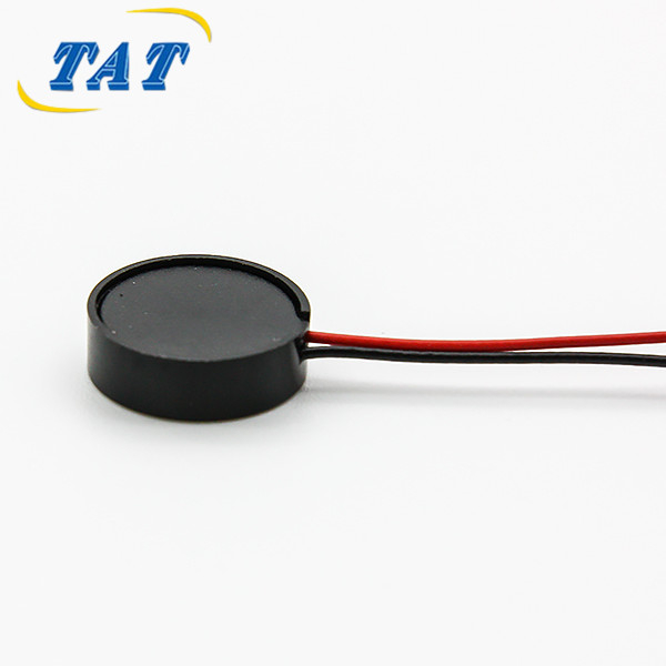
To navigate the complexities of acoustic component integration and ensure the final product meets its auditory requirements, engineering and procurement teams must adhere to a strict evaluation protocol. Relying solely on the buzzer sound pressure level at 10cm specification without validating the surrounding ecosystem is a recipe for project delays and field failures.
One of the most frequent errors made during the prototyping phase is failing to match the driving frequency to the component's mechanical resonance. If a component is rated for an SPL of 90dB at 2700Hz, driving it at 2500Hz or 3000Hz can result in a dramatic 10dB to 20dB drop in volume. Another typical oversight is neglecting the electrical demands of the component. Microcontroller general-purpose input/output (GPIO) pins often have strict current limits. If a magnetic component requires 30mA to reach its specified buzzer sound pressure level at 10cm, but the MCU pin can only source 10mA, the resulting sound will be weak and distorted.
Additionally, many design teams forget to account for the environmental stressors of the PCB assembly process. High-temperature wave soldering or reflow processes can induce thermal shock, potentially warping the plastic housing or altering the tension of the diaphragm. This thermal stress can permanently shift the resonant frequency or degrade the acoustic output, causing units that pass incoming quality control to fail final product acoustic testing.
To ensure PCB assembly success and robust acoustic performance, engineers should implement the following actionable advice:
Validate the Driving Circuitry: Always use an oscilloscope to verify the waveform across the component's terminals. Ensure the voltage swing is reaching the target levels and the frequency is locked onto the specified resonance. Utilize dedicated switching transistors (NPN or MOSFETs) equipped with flyback diodes for inductive magnetic components to ensure adequate current delivery and protect the driving MCU.
Conduct In-Situ Testing: Never rely on free-air acoustic tests. Measure the SPL only after the component is fully assembled inside the final, sealed product enclosure. Iterate on the acoustic port design of the chassis—adjusting the diameter, depth, and alignment of the sound holes—to minimize acoustic impedance and maximize volume projection.
Perform Thermal Profiling: Work closely with the contract manufacturer to ensure the soldering thermal profile strictly adheres to the acoustic component's datasheet limits. Consider implementing a post-assembly acoustic validation test in the quality assurance line to catch any heat-induced degradation immediately.
Engage Acoustic Experts: When sourcing, communicate your final product requirements (target SPL at 1 meter, enclosure type, driving voltage) to the supplier. A reputable manufacturer can often recommend a specific model or slightly modify a standard component’s resonant cavity to better match your unique application, ensuring the initial buzzer sound pressure level at 10cm translates into the desired real-world performance.
Understanding the baseline of a buzzer sound pressure level at 10cm is just the beginning of the acoustic engineering journey. While this standardized laboratory metric is crucial for comparing components side-by-side, it is not a direct guarantee of the final product's auditory performance. Achieving the perfect balance of volume, tone, and reliability requires a holistic approach that considers driving circuitry, PCB layout, chassis acoustic design, and rigorous in-situ testing. By recognizing the physical principles at play, understanding how lab data is generated, and carefully navigating the trade-offs between cost and performance, engineers can confidently select the right acoustic solution. Making informed decisions during the sourcing and prototyping phases ultimately ensures that the electronic product communicates effectively with the end-user, enhancing both safety and user experience while maintaining strict control over the final bill of materials.
While the decibel (dB) value is the primary indicator of volume, the most critical parameter to check in conjunction with the SPL is the rated resonant frequency. The specified buzzer sound pressure level at 10cm is only achievable when the component is driven exactly at this frequency. Additionally, you must verify the operating voltage and current consumption used to achieve that SPL, as driving the component with less power than specified will drastically reduce the acoustic output.
The requirement for a specific buzzer sound pressure level at 10cm directly impacts BOM cost in several ways. High-SPL components generally require tighter manufacturing tolerances, larger physical footprints, and more robust materials, which increases their unit price. Furthermore, a high-output magnetic component may draw significant current, necessitating the addition of dedicated driver transistors, flyback diodes, and potentially larger power supply capacitors to your PCB. Conversely, choosing a cheaper, lower-SPL component might require expensive and complex mechanical redesigns of the product housing to channel the sound effectively, shifting the cost from the electrical BOM to the mechanical tooling and plastics.


