
English 
Dedicated to global electroacoustic technology.
Views: 0 Author: Site Editor Publish Time: 2026-11-13 Origin: Site


A buzzer is a mechanical device before it is an electronic one. Inside the housing, a diaphragm or a ceramic disc is asked to move, and it will only move efficiently at the frequency it was tuned for. That single fact explains most of the arguments engineers have about buzzer volume, and it is the reason a datasheet number such as 2700 Hz matters more than the tone your firmware happens to output.
This article walks through what resonant frequency means on a buzzer datasheet, how the figure is actually measured, why comparing a 2.7 kHz part with a 4 kHz part on headline decibels is a mistake, and what to check before you commit a part number to a bill of materials.
Every buzzer has one frequency at which it produces the most sound for a given electrical input. Suppliers call it the resonant frequency, sometimes the rated frequency or f0, and it is the anchor for every acoustic number printed beside it.
A magnetic buzzer works like a small loudspeaker. A coil sits in a permanent magnetic field, an alternating current through the coil produces an alternating force, and that force pushes a diaphragm. A piezoelectric buzzer replaces the coil with a ceramic disc that changes thickness when voltage is applied. Both are mass-and-spring systems, and mass-and-spring systems have a natural frequency. Drive them at that natural frequency and the displacement builds up; drive them away from it and the same electrical energy produces far less movement, and therefore far less sound.
This is why the number on the datasheet is not a suggestion. It is the operating point the whole acoustic specification was written around. A 9.6 x 9.6 mm SMD magnetic buzzer such as the BMC9650S-0527 is listed at 2700 Hz with a tolerance of plus or minus 300 Hz, and its sound output of at least 85 dB at 10 cm is quoted at 5 VDC. Move the drive away from that band and the 85 dB figure no longer describes what you will hear.
The distinction between families matters here. An active buzzer contains its own oscillator, so the resonant frequency is fixed at the factory and the part simply sounds when powered. A passive buzzer has no oscillator, so the drive frequency you generate on the board becomes the tone, and it is your job to land that tone inside the resonant band. The SMD buzzer category splits along exactly this line, and picking the wrong side of it is the first place projects go wrong.
The decibel figure on a buzzer datasheet is a measurement, not a property. It only means something when you know the conditions attached to it.
Three conditions carry almost all of the weight: distance, drive level, and waveform. Distance is normally 10 cm, measured on the axis of the sound port, because sound pressure falls with distance and a figure quoted at 10 cm cannot be compared with one quoted at 1 m without correction. Drive level is the rated voltage, not the maximum the part will survive. Waveform is normally a square wave at a stated duty cycle, because a passive piezo element responds to the edge rate and to the peak-to-peak swing.
Take the BP9019S-40 passive piezoelectric buzzer as a concrete example. Its oscillation frequency is 4000 Hz, its operating voltage is 1 to 25 Vp-p with a rated voltage of 3 Vp-p, and its sound pressure level is a minimum of 65 dB at 10 cm measured at that rated voltage with a 50% duty square wave. Every one of those qualifiers is doing work. Change the drive to 1 Vp-p and the 65 dB number is no longer the specification; it is a hope.
The instrument itself matters as well. Sound level meters are classified and verified against IEC 61672-1, which defines how the meter weights and averages what it hears. Two labs using differently configured meters can disagree by several decibels on the same part without either of them being wrong. When a supplier and a customer disagree about a buzzer being quiet, the argument is usually about test conditions rather than about the hardware. Always confirm the current edition of any standard you rely on, and treat standard references as orientation rather than as a substitute for the agreed test procedure between you and your supplier.
Here is the trap. A buyer compares two lines on two datasheets: 85 dB against 65 dB, and concludes that the first part is dramatically louder. That conclusion may be right, but it is not supported by the comparison, because the two numbers were produced under different conditions on different transducer types.
The 2700 Hz magnetic part is specified at 5 VDC with a 30 mA current budget. The 4000 Hz piezo part is specified at 3 Vp-p and draws a maximum of 3 mA. You are comparing a magnetic transducer driven hard against a ceramic disc driven gently. The gap between the 85 dB figure and the 65 dB figure is real in the sense that both are honestly measured, but it is mostly a statement about drive power and transducer family, not about the frequency printed in the model name.
There is a second, subtler trap in the tolerance. A part listed at 2700 Hz with plus or minus 300 Hz covers 2400 Hz to 3000 Hz across a production run. If your firmware is hard-coded to output exactly 2700 Hz, most units will be close to resonance and some will sit at the edge of the band. If your firmware outputs 4000 Hz because that divider was already in the code, no unit in that band will be near resonance. The sound will still exist, it will simply be quieter than the datasheet promised, and the current draw may be higher than expected because the diaphragm is fighting the drive instead of reinforcing it.
For active parts the same problem appears in a different form. A magnetic buzzer with a built-in oscillator sounds at its factory-set frequency the moment you apply DC. You cannot retune it, and you cannot move it closer to the resonance of the enclosure you built around it. That is a feature when you want simplicity and a constraint when the acoustic design of the product changes late in the project.
The cost conversation usually starts with the transducer and ends with the driver, and it is worth having both on the table at once.
A piezo element is inexpensive, thin, and draws very little current, which is why it dominates battery-powered designs. A magnetic buzzer costs more in materials but produces more output per volt in the low-audio band, which is why it dominates alarms and industrial panels. If you choose piezo to save money and then discover you need considerably more output, the fix is usually a higher drive voltage or a resonant cavity, and both of those cost more than the difference between the two transducers.
The same logic applies to the drive circuit. A passive part needs a square wave, which costs you a timer channel and a firmware task. An active part needs only a GPIO and a supply, which costs you flexibility instead of money. Neither choice is universally cheaper; the cheap choice is the one that matches the acoustic target without a second design iteration.
Work through these before you lock a part number, and most of the surprises disappear.
Read the resonant frequency and its tolerance together. A centre frequency without the tolerance band tells you less than half the story.
Confirm the drive voltage in the SPL condition, then confirm your board can actually deliver it. A 3 Vp-p rating is not satisfied by a 3.3 V GPIO driving a piezo without accounting for the drive topology.
Match the tone to the enclosure, not to the desk. A part that is loud on the bench can be muffled by a sealed housing with a small port, and the port position affects which frequencies escape.
Check the current budget against the rest of the product. A 30 mA alert that fires continuously is a different power problem from a 3 mA one.
Confirm the mounting and termination match your assembly. SMD pads, pin mount and wire leads are not interchangeable on an existing footprint.
Ask for the test conditions in writing if the datasheet omits them. A number without conditions cannot be verified on receipt.
Verify the part number against the page or drawing you actually ordered from, not against a catalogue screenshot from an earlier project.
If the end product is a medical device with an alarm function, the acoustic alarm requirements live outside the buzzer datasheet. The alarm-systems part of IEC 60601-1-8 is the usual reference point; treat it as design guidance, confirm the current edition, and align it with your regulatory team before freezing the tone.
For teams that want the drive frequency handled for them, the BM5020S surface-mount electromagnetic buzzer is a useful reference point. Its page lists a rated voltage range of 1.5 V to 5 V, current consumption of 10 to 30 mA, a frequency range of 2 kHz to 4 kHz with plus or minus 2% stability, sound pressure level of 85 to 95 dB at 10 cm, an operational lifespan beyond 50,000 hours, and a high-temperature LCP housing suited to lead-free reflow. The stability figure is the interesting one: it tells you how much the operating frequency drifts, which is the property that makes a buzzer predictable in production.
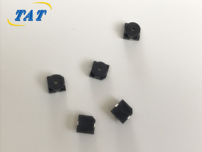
The side-facing sound port on this package is worth noting when you plan the mechanical layout. A port aimed at a wall or blocked by a connector will cost you more decibels than any datasheet tolerance, and no amount of drive voltage recovers it.
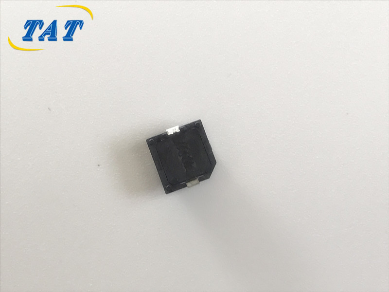
Resonant frequency is the single number that makes the rest of a buzzer datasheet true. A 2.7 kHz part beats a 4 kHz part when the 2.7 kHz figure is the frequency the part was tuned for and the 4 kHz figure is the tone your firmware happened to generate. Compare like with like: same distance, same drive level, same waveform, same transducer family. If you cannot state those four conditions for both parts, you are not comparing specifications, you are comparing marketing.
The practical rule is short. Find f0, respect its tolerance, drive it at rated voltage, and put the port where sound can leave the box. Everything else on the datasheet is downstream of those four decisions.
What happens if I drive a buzzer below its resonant frequency?
Output falls. The diaphragm still moves, so you will hear something, but the displacement per unit of electrical input is lower than at resonance, and the sound pressure at 10 cm will not match the datasheet figure. Depending on the drive circuit, current may rise because the load is more reactive away from resonance.
Can I use a 4 kHz drive signal on a 2700 Hz magnetic buzzer?
You can, and the part will make a sound, but you will be operating outside its resonant band and should expect reduced output. If the alert must be audible in a noisy environment, either move the drive into the resonant band or select a part whose resonant frequency matches the tone you need.
Why do two suppliers quote very different decibels for similar-looking buzzers?
Because the numbers were measured under different conditions. Check distance, drive voltage, waveform and transducer type before drawing a conclusion. A magnetic part at 5 VDC and a piezo part at 3 Vp-p are not in the same comparison at all, and a spec sheet that omits the conditions cannot be used for selection.
Does a higher frequency sound more urgent?
That is a perception question rather than an acoustic one, and perception depends on the enclosure, the background noise and the listener. What is measurable is that a part produces its rated output at its own resonant frequency. Choose the tone for the product, then choose a part that resonates there, rather than choosing a frequency first and hoping the part follows.
How do I confirm a delivered batch actually meets the datasheet?
Measure at the stated conditions: rated voltage, stated waveform, 10 cm on axis, with a meter you trust and a documented procedure. Compare like for like against the supplier's stated conditions, and keep the record. If the numbers disagree, the first question is always which of the conditions differed.


