
English 
Dedicated to global electroacoustic technology.
Views: 0 Author: Site Editor Publish Time: 2026-11-12 Origin: Site


Most audible-alert designs that must run from a coin cell end up with a boost converter in front of the buzzer. It works, but it adds a switching node, an inductor, a bill-of-materials line and a quiescent draw that keeps eating the cell while the product sits idle. The alternative is to pick a transducer whose rated drive already sits at the cell voltage, so the alert runs straight off the rail.
The TAT BM9650E-0127-5.5 is specified for exactly that case: 1.5 Vo-p rated inside a 1 – 3 Vo-p operating window, with a claimed ≥ 90 dB at 10 cm at that drive level. This article works through the datasheet line by line, states what each figure does and does not promise, and shows where the driver circuit usually goes wrong.
A coin cell is a high-impedance source. Its internal resistance is large enough that a sudden burst of load current drags the terminal voltage down, and the microcontroller sharing that rail sees the droop as a brownout. In practice that is why designers reach for a boost converter: not because the buzzer needs a higher voltage to be loud, but because a part rated at 12 Vo-p cannot be driven from a 1.5 V rail at all without one.
Two figures decide whether the boost stage is needed. The first is the rated voltage, which must sit close to the cell voltage so the drive amplitude stays available as the cell discharges. The second is the coil impedance, because that sets how much current the alert pulls during each half-cycle. A part with a rated drive at the cell voltage and a low-impedance coil can be driven from the rail directly, and the droop stays inside what the MCU tolerates.
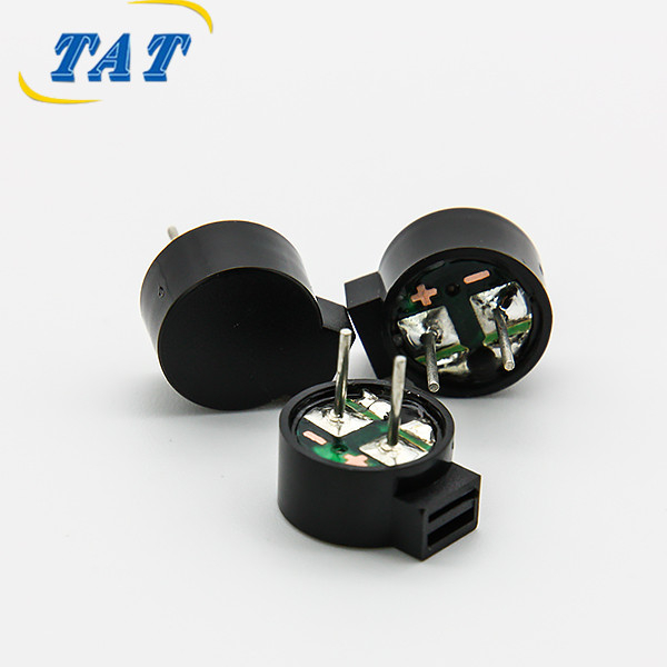
The part is a passive electromagnetic buzzer without an internal drive circuit, in a Φ9.6 mm × 5.0 mm body with a potted top and a black PBT housing. The full specification as published on the TAT BM9650E-0127-5.5 product page reads as follows.
Parameter | Specification |
|---|---|
Buzzer type | Passive electromagnetic, without circuit |
Rated voltage | 1.5 Vo-p |
Operating voltage | 1 – 3 Vo-p |
Rated current | ≤ 80 mA at 2.731 kHz, 50% duty, 1.5 Vo-p |
Sound output | ≥ 90 dB at 10 cm at 2.731 kHz, 50% duty, 1.5 Vo-p |
Coil resistance | 5.5 ± 1 Ω |
Resonant frequency | 2731 Hz |
Body diameter | Φ9.6 ± 0.2 mm |
Body height | 5.0 mm |
Top | Potted seal |
Mounting | Through-hole pins, L1 = 3.0 ± 0.5 mm, Φ0.6 ± 0.1 mm, spacing 5 ± 0.2 mm |
Housing material | Black PBT |
Net weight | Approx. 1.5 g |
Operating temperature | −20 °C to +70 °C |
Storage temperature | −30 °C to +80 °C |
Three of those rows carry almost all of the design risk, and each one is conditional.
The 90 dB at 10 cm figure is quoted at 2.731 kHz, 50% duty and 1.5 Vo-p — that is, at the mechanical resonance of the assembly, with a symmetric square wave, at the rated voltage. Move the drive off resonance and the output falls; halve the drive amplitude and it falls further. The number describes the peak of a curve, not a floor that follows you around the operating range. The measurement convention behind a sound-level figure of this kind is standardised, and IEC 61672-1:2013 is the reference for sound level meters and the way SPL is measured.
The ≤ 80 mA figure is conditional in the same way, and this is where circuits fail. It is quoted at resonance with a 50% duty square wave, not for a steady DC level. Hold a DC voltage across a 5.5 Ω coil and the current that flows is set by resistance alone, with no duty cycle to average it down, and no back-EMF from the diaphragm in motion. A part that is comfortably inside its rating under correct drive can overheat under a stuck-high pin.
The 1 – 3 Vo-p operating window is what makes the coin-cell application work. The cell starts near 1.5 V or above and sags over its life; a rated drive at 1.5 Vo-p with an operating range that extends down to 1.0 Vo-p keeps the alert audible across that discharge without any regulation.
A passive buzzer contains no oscillator. Applied DC produces one mechanical deflection and then nothing — the click that engineers describe as a dead part. To get a tone, the coil must be driven with a square wave at the resonant frequency, and the host owns both the frequency and the duty cycle.
That is a limitation and an advantage at the same time. It costs you a PWM channel or a small oscillator. It gains you tone control: patterns, chirps, multi-level alerts and silent-when-idle behaviour all come from firmware rather than from a second part number.
The five claims that matter for a low-voltage product are all traceable to the table above. Read together, they describe a part that removes work from the board rather than adding it.
Design constraint | What the part offers | What it saves you |
|---|---|---|
Rail is a single 1.5 V cell | Rated 1.5 Vo-p, operating 1 – 3 Vo-p | The boost converter and its inductor |
Loud alert required at low voltage | ≥ 90 dB at 10 cm at 1.5 Vo-p | An amplifier stage and its headroom |
Very little board area | Φ9.6 × 5.0 mm body | Relayout of the acoustic keep-out |
Dust and moisture in the field | Potted top, black PBT housing | A secondary conformal coating step |
Assembly differs between models | Pin, wire-lead or connector termination | A board respin per variant |
The rated voltage is the cell voltage. That is the whole argument for the part: the discharge curve of a single alkaline or coin cell stays inside the 1 – 3 Vo-p window for the useful part of its life, so the alert can be driven straight from the rail with a transistor and nothing else.
Ninety decibels at 10 cm is a clearly audible alert in a quiet room and remains audible over typical indoor background noise. The point is not the absolute figure but where it comes from: a 5.5 Ω coil driven at resonance at 1.5 Vo-p. Efficiency here is mechanical, and it is why the part does not need a higher rail to be loud.
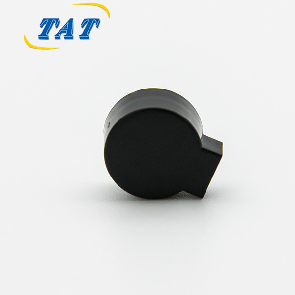
A 9.6 mm diameter and 5.0 mm height fits inside slim handheld and wearable enclosures, and the round body lets you place it in a corner where a rectangular sounder would not go. Two things still need space: the acoustic path to the outside, and clearance for the pins. Both are enclosure decisions, not buzzer decisions, and both are usually discovered late.
The top of the part is potted, which keeps dust and moisture out of the coil cavity, and the housing is black PBT. The operating window is −20 °C to +70 °C with storage from −30 °C to +80 °C. That covers indoor equipment and most outdoor electronics in temperate climates.
It is worth being precise about what potting is not. It is not a sealing rating. If the product is exposed to rain, washdown or condensation, the potting helps but the enclosure still needs an acoustic membrane or mesh vent sized for the sound path — and the SPL figure has to be re-checked with that membrane in place, because a mesh that keeps water out also attenuates the tone.
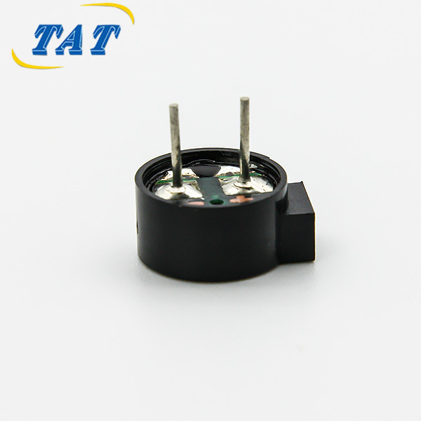
The standard termination is two through-hole pins, 3.0 ± 0.5 mm long, Φ0.6 ± 0.1 mm, on 5 ± 0.2 mm spacing — a footprint that is easy to hand-solder and easy to wave-solder. Wire-lead and connector versions exist for assemblies where the buzzer cannot sit on the main board, which matters in designs where the sound has to come from a specific face of the enclosure.
The drive stage is a low-side switch. One buzzer pin goes to the positive rail, the other to the drain of a small N-channel MOSFET or the collector of an NPN transistor, with the source or emitter to ground. The MCU pin drives the gate or base through a resistor and never touches the coil directly.
Three details separate a working circuit from a returned one.
Drive at the resonant frequency, with a real 50% duty cycle. A firmware timer that produces 2.731 kHz but a 20% duty cycle delivers less energy per cycle than the datasheet condition, and the alert will be quieter than expected. Verify the waveform at the buzzer terminals with a scope, not at the MCU pin.
Add a catch diode across the coil. The coil is inductive; interrupting its current produces a voltage spike at the switch. A diode across the coil terminals gives that energy a path and protects the transistor.
Do not leave the output high in a failure state. If firmware can park the pin high — a crash, an uninitialised port, a bootloader that holds the pin — the coil sees DC and the current is limited only by 5.5 Ω. Either default the pin to input, or put the switch behind a gate that is off until firmware enables it.
If the alert is a medical alarm, the target SPL is not the datasheet figure. IEC 60601-1-8 sets out how alarm signals in medical electrical equipment must be measured and what the audible requirements are, and compliance is judged in the finished enclosure with the real acoustic path — not on an open bench.
The part suits battery-powered devices where the rail is one cell and the alert is short and occasional: key fobs, greeting cards, tyre-pressure monitors, glucose meters and thermometers, blood-pressure monitors, smart locks, timers and wearable accessories. In most of those the alternative is a 3 V or 5 V part plus a converter, and the part list gets shorter with this one.
It is the wrong choice in four situations, and each has a specific answer.
If the enclosure must survive water rather than dust and moisture, the potting is not enough and the design needs an acoustic membrane plus a re-measured SPL budget.
If the rail is 5 V rather than 1.5 V, the same 9.6 mm footprint is available in the BMC9650-0527, a passive magnetic part at 9.6 × 9.6 × 5.0 mm rated for 5 V, which keeps the mechanical design and changes only the electrical one.
If the tone must sit at 2731 Hz in a larger body with a higher rail, the BM1275E-0327-16 resonates at the same frequency and is rated for a 3 Vo-p drive.
If the firmware team would rather not generate a tone at all, the answer is an active part with an internal oscillator, which trades tone control for a single DC enable line. The magnetic buzzer range covers both families, and the passive-versus-active split is the first decision to make before comparing dB figures.
Confirm the rail voltage across the whole battery life, not just at full charge, against the 1 – 3 Vo-p window.
Confirm the target SPL is required at 10 cm or at a different distance; the figure does not transfer.
Confirm the acoustic path: grill open area, membrane or mesh, and the distance from the diaphragm to the outlet.
Confirm the termination before tooling: pins, wire leads or connector changes the assembly process.
Confirm the temperature range in the enclosure, which is usually warmer than ambient by the internal dissipation of everything else on the board.
The interesting thing about the TAT BM9650E-0127-5.5 is not that it is loud for its size. It is that the rated drive voltage matches the cell, which removes a converter, an inductor and a source of quiescent loss from a low-power design. The price of that is a driver you must design correctly: a square wave at 2731 Hz, a proper low-side switch, and a firmware default that cannot park the coil across the rail. Get those three right and the alert is a component on the BOM rather than a subsystem.
No. It is a passive part without an internal oscillator, so a steady DC level produces one deflection and no tone. It needs a square wave at 2731 Hz, and the datasheet figures are quoted at 50% duty. Driving it with DC also removes the duty cycle that keeps the average current inside the ≤ 80 mA rating.
Because the rated voltage is 1.5 Vo-p and the operating window is 1 – 3 Vo-p, which is where a single cell spends its life. A buzzer rated at 12 Vo-p would need a converter to reach its rated drive; this one does not. The ≥ 90 dB at 10 cm figure is quoted at that same 1.5 Vo-p drive.
Switch it, do not bias it. Use a low-side NPN or N-channel MOSFET, drive the gate or base from the MCU through a resistor, add a catch diode across the coil, and make sure a crashed firmware state cannot leave the switch on. The rated current assumes resonant drive at 50% duty.
It keeps dust and moisture out of the coil cavity and it is the right choice for dusty or humid equipment, but it is not a sealing rating. Products exposed to rain or washdown still need an acoustic membrane in the enclosure, and the SPL should be verified with that membrane fitted.
Yes. The standard version is through-hole pins on 5 ± 0.2 mm spacing, 3.0 mm long; wire-lead and connector terminations are available for assemblies where the buzzer has to sit away from the main board.


