
English 
Dedicated to global electroacoustic technology.
Views: 0 Author: Site Editor Publish Time: 2026-11-16 Origin: Site


A buzzer is one of the cheapest components on a board, and one of the easiest to mis-budget. Teams routinely reserve a few milliamps for the audible indicator, then discover at the battery-life test that the part is drawing an order of magnitude more than the number they remembered. The confusion is rarely about the part itself. It is about which number on the datasheet was read, and under what conditions that number was produced.
This article works through the three load classes that appear most often in sourcing conversations, roughly 1 mA, 30 mA and 100 mA, and explains what each one actually tells you about a design. Along the way it uses measured figures from our own catalogue so the discussion stays on real parts rather than abstractions.
Current draw on a buzzer is not a single fixed property. It is the result of a circuit, a drive waveform and a measurement condition, and all three have to match before two numbers can be compared.
Piezoelectric and electromagnetic buzzers consume current for completely different reasons, and that difference explains most of the spread you see across a catalogue.
An electromagnetic buzzer contains a coil. Driving it means pushing current through a winding, so the steady-state draw is set by coil resistance and applied voltage, and the part behaves much like a small inductor with a resistive loss term. Current flows continuously while the tone sounds.
A piezoelectric element is a capacitor. It does not need a standing DC current to maintain a tone. What it needs is a changing voltage across a ceramic disc, which means the supply charges and discharges a capacitance on every half cycle. The average current therefore scales with capacitance, drive voltage and frequency, and it is often small enough that the driver stage dominates the power budget rather than the buzzer.
That is why a passive piezo such as the BP1770C-0540 can be quoted at a maximum of 5 mA while driven by a 4.0 kHz, 50% duty square wave at 5 Vp-p, with a capacitance of 15000 pF plus or minus 30% measured at 120 Hz and 1 V. The part is not consuming 5 mA the way a resistor would. It is being charged and discharged, and the figure is the average that results from that activity at the stated drive.
Active buzzers add a third layer. A built-in oscillating circuit generates the tone internally, so the part accepts DC directly, but the internal oscillator and driver now draw their own quiescent current. A 12 VDC active piezo like the BPC2310 is rated for a maximum of 15 mA at 12 VDC, and the BPC1475-1240 is rated for a maximum of 10 mA at 12 VDC. Both figures sit in the same order of magnitude even though the two parts deliver 90 dB and 85 dB at 10 cm respectively, because in both cases you are paying for an oscillator plus a ceramic load.
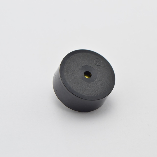
The practical consequence: when someone says a buzzer "draws about 30 mA", ask which family. A 30 mA figure on a magnetic part and a 30 mA figure on a piezo part arrive from opposite directions, and they behave differently when you change voltage, frequency or duty cycle.
Every current figure in a catalogue is a measurement, and the conditions travel with it. Strip the conditions away and the number becomes a rumour.
Four variables move the reading more than anything else.
The first is the applied voltage. Current on a coil-based part scales roughly with voltage, so a maximum quoted at 12 VDC tells you very little about behaviour at 24 VDC. On a piezo part the relationship is closer to proportional to voltage as well, because charge per cycle scales with the voltage swing, but the shape of the curve is different and the driver's own losses start to matter.
The second is the drive waveform. A passive piezo driven by a square wave at its resonant frequency will draw a different average current than the same part driven by a sine wave or driven off resonance. The BP1770C-0540 figure of 5 mA is explicitly tied to a 4.0 kHz, 50% duty square wave at 5 Vp-p. Change the duty cycle and the average current changes with it, because average current on a capacitive load follows the charge delivered per unit time.
The third is whether the part is active or passive, and if active, whether the internal oscillator is running. A part held in a silent state is not drawing the same current as a part sounding continuously.
The fourth is the acoustic test distance, which does not change current at all but is frequently quoted in the same breath. Sound output on our parts is stated at 10 cm, so a 90 dB figure and an 85 dB figure are only comparable when both were taken at that distance with instrumentation that conforms to the sound level meter requirements of IEC 61672-1.
One more condition deserves a mention even though it sits outside the electrical measurement. When the indicator is part of a medical device, the alarm behaviour of the finished system is governed by IEC 60601-1-8, which addresses alarm signals and the conditions under which they must remain audible. We treat that as a system-level question and refer readers to the published standard, with the usual reminder that the edition in force governs.
A current number without a voltage, a waveform and a tone state is not a specification. It is a hint.
The most common misreading is treating a maximum as a typical. A line that reads "Max. 30 mA at 24 VDC" describes an upper bound across the production spread and the stated conditions. A typical unit may well sit below it. Design your supply for the maximum, then confirm the typical with a sample measurement on your own board.
The second misreading is comparing parts across families. An active piezo rated at 15 mA and a magnetic transducer rated at 15 mA will not behave the same way when you halve the supply voltage, because one is dominated by an oscillator and a ceramic load and the other by a coil.
The third is ignoring the driver. On a passive piezo, the transistor, the series resistor and the switching frequency can contribute more current than the buzzer itself. A design that looks efficient on the buzzer line item can still lose milliamps in the drive stage.
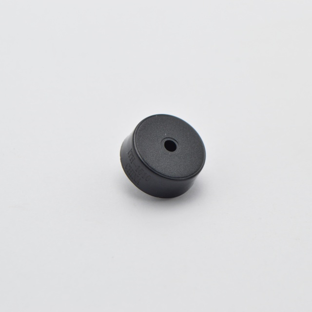
Current draw is one axis of a three-way trade with loudness and unit cost, and the trade is not linear.
If a design needs the highest output available in a small package, an active piezo with a larger ceramic disc is usually the efficient route: the BPC2495W100-2435 reaches a minimum of 95 dB at 10 cm while its rated current peaks at 30 mA at 24 VDC. Thirty milliamps on a 24 V industrial rail is unremarkable, and a single PLC output point will typically carry several such units.
If the design runs from a coin cell or a small lithium pack, that same 30 mA is a different proposition. The passive route becomes attractive: a part like the BP1770C-0540 shifts the burden to the driver stage, where you can choose how hard to push the disc, and its wide 1 to 30 Vp-p drive range means the same part can be re-tuned later without a re-source.
If the design is cost-sensitive and runs on a mains-derived rail, a 12 VDC active part at 10 to 15 mA is often the cheapest way to get 85 to 90 dB with no external circuitry at all, because the bill of materials collapses to the buzzer and a decoupling capacitor.
None of these choices is universally right. The trade only resolves once the supply, the required loudness and the expected duty cycle are all known.
Do the arithmetic before the layout, not after.
Start from the average current, not the peak, when the question is battery life. For a continuous-tone alarm that sounds for ten seconds per event, the average contribution to the daily budget is tiny even at 30 mA. For a part that sounds for minutes at a time, or sounds continuously during a fault condition, the same figure becomes the dominant load.
Then add the duty cycle of the drive. On a passive piezo, average current tracks how often you charge the disc, so a lower drive frequency or a gated tone reduces consumption in a way that is not available on an active part with a fixed internal oscillator.
Finally, account for the regulator. A 30 mA load on a linear regulator fed from a much higher rail dissipates more heat than the buzzer consumes, and on a small board that thermal path is often the real constraint. Switching the buzzer to a lower rail, or choosing a part with a wider operating voltage so it can sit directly on the existing rail, usually removes the problem entirely.
A short list, in the order that saves the most time.
Parts built around these questions are collected in our piezoelectric and magnetic buzzer range, and each product page states the voltage, current, frequency and test distance behind its figures.
The gap between 1 mA, 30 mA and 100 mA is not a gap in quality. It is a gap in circuit topology, drive strategy and measurement convention. A passive piezo drawing a few milliamps under a square-wave drive, a 12 VDC active part at 10 to 15 mA, and a 24 V industrial part at 30 mA all describe the same physical job performed under different constraints.
Read the number with its conditions attached, budget for the maximum, and verify one sample. That sequence settles the question faster than any catalogue comparison, and it keeps the audible indicator from becoming the surprise in the battery-life report.
It depends on how the part is held silent. If the supply is removed or switched off, no current flows. If the supply stays connected and the part is merely not driven, an active part with an internal oscillator may still draw a small quiescent current, and that figure is not the same as the rated current at full tone. Ask for both numbers if the indicator spends most of its life silent.
Because the capacitor is being charged and discharged continuously while the tone sounds, and the average of that charge movement is a current. The figure is meaningful only alongside the drive voltage, frequency and duty cycle, which is why the BP1770C-0540 listing pairs its 5 mA maximum with a 4.0 kHz, 50% duty square wave at 5 Vp-p.
Not directly on the buzzer's rated rail, and not directly from a GPIO at all for most parts. Active buzzers with a wide operating range can often be run below their rated voltage with reduced output, but the GPIO pin itself is not a power source for a part drawing milliamps of continuous current. Use a transistor or a dedicated driver, and size it for the maximum current rather than the typical.
For very low average current, a passive piezo driven efficiently is hard to beat, because the element itself stores energy rather than dissipating it. For a fixed DC supply and no external circuitry, an active piezo in the 10 to 15 mA class typically delivers 85 to 90 dB at 10 cm with the simplest bill of materials. The right answer follows the supply and the duty cycle, not a single ranking.
The rated current on a catalogue page is quoted at a nominal condition, not across the full operating range. Coil resistance and ceramic behaviour both shift with temperature, and the internal oscillator of an active part is not perfectly temperature independent. If the indicator must work at the edge of its rated range, include a margin and confirm the behaviour at that temperature with a sample.
No. It is a sign of a different design choice. A part drawing 30 mA at 24 VDC is delivering a minimum of 95 dB at 10 cm in a 30 mm class package, and that output is the point. A part drawing 5 mA is trading some of that headroom for a battery-friendly load. Neither number is a quality grade on its own.


