
English 
Dedicated to global electroacoustic technology.
Views: 0 Author: Site Editor Publish Time: 2026-11-06 Origin: Site


The smd buzzer vs through hole buzzer question almost always arrives too late. Most design teams choose an audible part from its acoustic data — sound pressure level, resonant frequency, rated voltage — and only then hand the footprint to the DFM review, where somebody points out that the part needs 5 mm of pin tail below the board, or that the reflow profile will cook a diaphragm rated for hand soldering only.
That order is backwards. Acoustic numbers are negotiable inside a product family: the same coil, cavity and diaphragm can be tuned across a range of frequencies and voltages. The mounting route is not negotiable, because it is locked by the SMT line, the soldering process, the panel layout, the enclosure height and the vibration specification. Changing it after tooling exists is the expensive kind of change.
This guide works through the six trade-offs that actually decide the choice, using real parts from a single supplier catalogue so the comparison stays honest — same transducer family, different package.
There are only two ways to attach a buzzer to a board. It is either placed and reflowed with the rest of the SMT components, or it is inserted through plated holes and soldered afterwards, by wave or by hand.
Everything else follows from that one fact. A through-hole part needs a hole pattern in the board, clearance on the solder side, and a process step that happens after the reflow oven. A surface-mount part needs a land pattern, a reel or tray that survives the oven, and heat resistance inside the component itself.
The acoustic consequence is smaller than most people expect. An electromagnetic buzzer of a given diameter produces roughly the same output whether its terminals are pins or pads, because the sound comes from the diaphragm and cavity, not from the lead frame. What changes is how much of that output survives the enclosure, the coating and the assembly process. That is what the six trade-offs below are really measuring.
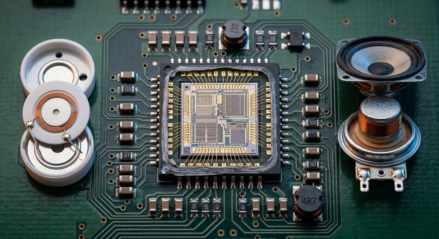
Surface mount wins the obvious comparison, but not by the margin people assume.
A through-hole part consumes area on both sides of the board. The body sits on the top side, and every pin needs a solder joint plus a cut lead on the bottom side. A part with a 5 mm pin extension effectively needs about 11.5 mm of clear vertical space once you add the body height, the board thickness and the protruding tip. In a slim enclosure that number is often the single largest vertical constraint on the whole design.
Surface-mount parts still occupy the top side, but they stop at the board surface. Parts from the SMD buzzer range show how tight this gets:
Part | Package | Outline | Height | Board-side clearance |
|---|---|---|---|---|
BM4020S-0340-17 | SMD | 4.0 ± 0.3 mm × 2.0 ± 0.3 mm | 2.2 mm | None below the board |
BM5030S-0340-12 | SMD | 5.0 × 3.0 mm | Low profile, 3 pads | None below the board |
BM7525S | SMD, 7525 footprint | Compatible with 9 mm / 12 mm layouts | Low profile | None below the board |
BMC1265-0527 | DIP, through-hole | Φ12 mm body | 6.5 mm body + 5 mm pin extension | ~11.5 mm total stack |
The BM4020S-0340-17 case is worth pausing on. A 4.0 × 2.0 mm outline at 2.2 mm height is small enough to sit between other components rather than forcing a keep-out zone, which matters more than raw area: a part you can nest is cheaper than a part you have to reserve space for.
One practical warning. When you measure clear height, measure to the tallest neighbouring component, not to the average board height. A buzzer that fits under an enclosure lid but collides with a 6 mm electrolytic capacitor two millimetres away is not a design that fits.
This is the trade-off that produces the most field failures, and it is invisible on a datasheet summary.
A surface-mount buzzer goes through the reflow oven with the rest of the board. That means the entire component body — coil, diaphragm, potting compound, plastic housing — sees the full peak temperature, and on a double-sided board it may see that profile twice. The published tolerance for the BM7525S is up to 260 °C with lead-free compatibility, which is the kind of figure you should look for explicitly rather than assume.
A through-hole buzzer avoids the reflow oven entirely, because it is inserted after the SMT stage. Its pins do see molten solder — during wave soldering, or under a hand iron — but for a few seconds and only at the terminals, which are metal. The heat path into the diaphragm is short but narrow.
The failure mode when this is got wrong is not a dead part. It is a part that still works but has drifted: resonant frequency shifted by a few hundred hertz, output down several decibels, or an intermittent coil connection that only appears after thermal cycling. None of that shows up in a first-article inspection.
Process question | SMD buzzer | Through-hole buzzer |
|---|---|---|
Sees reflow peak temperature | Yes — whole body | No |
Sees wave solder | Usually no | Yes — pins only |
Sees hand-solder iron | Only for rework | Often, during assembly |
Number of thermal passes | 1–2 (double-sided board) | 1 |
Main risk | Diaphragm and potting drift | Localized heat damage at terminals |
What to request from the supplier | Max reflow peak, time above liquidus, rated passes | Recommended iron tip temperature and dwell |
Ask for those numbers in writing. A supplier who cannot state a reflow peak and a pass count has not characterised the part for your process, and no amount of acoustic data compensates for that.
Here through-hole has a genuine structural advantage that no amount of process optimisation removes.
A pin through a plated hole, soldered on the far side, resists pull-out in shear along the full barrel of the hole. A solder pad resists only the peel and shear strength of a thin intermetallic layer. Under vibration, a surface-mount part is held by two or three small joints that see the full mass of the component as an alternating load; a through-hole part distributes that load into the board thickness.
This is why through-hole parts still dominate in appliances with motors, in equipment that gets dropped, and in anything with a shipping vibration specification written into the purchase order.
The surface-mount route can close most of that gap, but it takes deliberate design:
More pads, spread wider. The BM5030S-0340-12 uses three tin-plated brass soldering pads rather than two. Three pads constrain rotation as well as translation, and they also fix polarity orientation mechanically.
A mounting boss. A moulded post in the enclosure that contacts the top of the housing turns a peel load into compression. This is the cheapest fix available and is usually designed out too early.
An adhesive dot or underfill. Effective, but it adds a process step and makes rework destructive.
A drop-in footprint. The BM7525S uses a 7525 footprint compatible with 9 mm and 12 mm layouts, which means it can replace an older through-hole part in the same board area without a redesign.
The decision rule is simple. If the board flexes under load, or the enclosure resonates near the drive frequency, either specify through-hole or design a boss. Do not rely on solder pads alone and hope the vibration test is gentle.
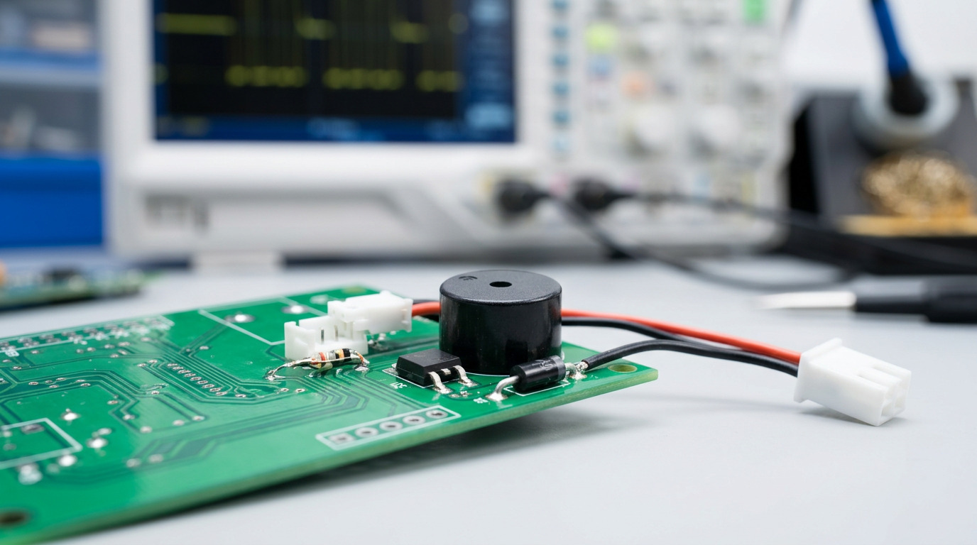
This is where surface-mount designs quietly lose the output the datasheet promised, and where through-hole designs quietly earn their keep.
Sound has to leave the package along a defined axis. On the BM4020S-0340-17 that axis is marked: the part carries both a polarity mark and a designed sound port. Rotate that port under a sealed cover and the acoustic path is blocked — the part still works, the measurement still passes at the bench, and the finished unit is noticeably quieter than the prototype.
Through-hole parts often solve this by construction. The BMC1265-0527 is potted with a centre emission hole: the potting seals the diaphragm from the environment, and the hole defines a single, predictable radiation axis that a designer can align with a grill.
Sealing matters as much as porting. Conformal coating and board washing are the two processes that kill buzzers, and neither appears on an acoustic datasheet. A potted part with a sealed top survives coating because the diaphragm is already encapsulated. An open surface-mount part may take coating straight into the port, stiffening the diaphragm permanently.
Two more numbers decide whether the acoustic result survives assembly:
Reference distance. Output figures are quoted at a reference distance such as 10 cm. If the physical port sits 3 mm behind a plastic wall, the number at the user's ear is a different number, and the difference is a function of your enclosure, not the part.
Drive condition. A figure quoted at 12 VDC and a figure quoted at 3.0 Vo-p are not comparable, even when they appear in the same table. Always port the test condition along with the value.

Panel design changes once a tall component enters the picture.
Surface-mount buzzers are reel-fed and placed like any other part, which is the whole point: no manual step, no extra station, no operator judgement. The costs are subtler. A part several millimetres tall can be knocked loose during panel handling, and reflow shadowing becomes a real concern when it sits downwind of taller components. Both are solved by placement rules, not by part selection.
Through-hole adds a process step. On a wave-soldered board that step is nearly free. On a reflow-only line it becomes a hand-soldering operation, and hand-soldering a piezo or electromagnetic buzzer carries a specific risk: the iron sits close to the diaphragm, two pins allow the body to tilt before the solder freezes, and the operator has no way to see the damage being done.
Fixed pin geometry is the mitigation. A part with 7.6 mm pin spacing (BMC1265-0527) or 10.5 mm pin spacing with a 3.1 ± 0.5 mm pin length (BP1770C-0540) cannot be inserted at an angle without the holes refusing it. That is a design feature disguised as a dimensional tolerance.
Rework tells a similar story in reverse. Desoldering a through-hole part is trivial but requires clearing two holes. Removing a surface-mount part needs hot air and a nozzle that does not blow into the sound port — a small detail that decides whether a reworked unit passes acoustic test afterwards.
Unit price is the least useful number in this comparison.
The real cost of a buzzer is the sum of the part price, the placement step, the soldering step, the acoustic test yield, the fallout rate, the board area consumed, and the enclosure height it forces. Several of those items are larger than the part price itself.
At volume, surface mount usually wins because it removes a manual station entirely, and manual stations scale with labour cost rather than with unit count. Below a few hundred units, through-hole frequently wins: no stencil, no reel minimum, no reflow profile validation, no thermal characterisation of a part that will be hand-soldered anyway.
There is one cost that gets missed consistently. A through-hole part needs clearance on the solder side, and in a slim product that clearance becomes enclosure geometry — a taller housing, a cutout, or a separate internal bracket. That is tooling money, and it is paid once per product, which means it dominates the comparison at low volume and disappears at high volume.
Volume band | Usually lower total cost | Why |
|---|---|---|
Prototype and pilot (tens) | Through-hole | No stencil, no reflow validation, hand assembly already happening |
Low volume (hundreds) | Through-hole, unless enclosure height is critical | Tooling amortisation is still poor |
Mid volume (thousands) | Surface mount | Manual soldering station removed |
High volume (tens of thousands) | Surface mount | Placement is effectively free; manual steps are not |
Comparing two parts from the same catalogue isolates the mounting variable, because both are electromagnetic buzzers with the same underlying transducer principle. One is surface mount, one is a DIP part.
Parameter | BM5030S-0340-12 (SMD) | BMC1265-0527 (DIP) |
|---|---|---|
Mounting | SMD surface mount, 3 soldering pads | Through-hole, 2 × Φ0.6 mm pins, 7.6 mm spacing, 5 mm extension |
Rated voltage | 3.0 Vo-p | 5 VDC |
Operating voltage | 2.0 – 5.0 Vo-p | 1 – 12 VDC |
Rated current | Max. 100 mA at 3.0 Vo-p, 4000 Hz, 50% duty square wave | Max. 30 mA at 5 VDC |
Output | Min. 80 dB at 10 cm, at rated condition | 85 dB at 10 cm |
Frequency | 4000 Hz | 2700 ± 300 Hz |
Coil resistance | 12 ± 2 Ω | Not stated on the summary |
Operating temperature | −30 °C to +70 °C | Not stated on the summary |
Storage temperature | −40 °C to +85 °C | Not stated on the summary |
Mass | Approx. 0.3 g | Body Φ12 mm × 6.5 mm |
Housing | Black LCP | Potted seal, centre emission hole |
Terminals | Tin-plated brass pads | Φ0.6 mm pins, 5 mm extension |
Three observations come out of that table, and each of them contradicts an assumption engineers commonly bring to this decision.
Surface mount does not mean lower current. The SMD part draws up to 100 mA while the through-hole part draws 30 mA. Current is set by the coil design and the drive condition, not by the package. Anyone who assumes a smaller package means a smaller load on the driver circuit will be surprised by a factor of three.
The through-hole part has the wider voltage window. 1 – 12 VDC versus 2.0 – 5.0 Vo-p. If the design has an unregulated supply that sags, the wider window is worth more than the millimetres saved.
Frequency is a separate decision. 2700 Hz and 4000 Hz sit in different parts of human sensitivity, and neither is inherently better. What matters is that the frequency you specify has a tolerance you can live with — a ±300 Hz window around 2700 Hz is a different commitment from a part characterised to a tighter band.
Despite the volume economics, there are configurations where a through-hole part is the correct engineering answer and surface mount is the compromise:
The line has wave soldering but no reflow capability.
The enclosure cannot provide clear height on the component side, so the part must sit low and the pin tail can exit into a cavity.
The vibration or drop specification leaves no room for a mounting boss.
The product is field-serviceable and parts are replaced by hand.
Total volume is low enough that no tooling change is justified.
The assembly is washed and coated, and no equivalent sealed surface-mount part is available with the required port geometry.
Notice that four of those six are process facts, not preferences. That is the signature of a decision that should be made by manufacturing engineering early, and defended later.
Six errors account for most of the buzzer rework we see in assembly feedback:
Comparing output figures measured under different drive conditions. 85 dB at 12 VDC and 80 dB at 3.0 Vo-p cannot be ranked against each other. Match the test condition before comparing the number.
Confusing VDC and Vo-p. A passive part driven by a square wave is characterised in peak-to-peak terms. Reading the VDC figure and driving with a square wave can double the applied voltage.
Assuming surface mount is quieter. Package size does not set output. Coil, cavity and drive condition do.
Forgetting the port after the enclosure is sealed. A part with a defined emission axis has to be oriented, and the orientation has to survive the drawing review.
Taking values from the summary block instead of the detailed table. On many product pages the top parameter block and the full specification table disagree on tolerance or test condition. The detailed table is the one written from the test sheet, so verify against it before the number enters your BOM.
Not asking whether the reel or tray is rated for your oven. Component-level reflow tolerance and packaging-level reflow tolerance are two different specifications.
Before the buzzer line is frozen, confirm each of these against the actual drawing and the actual process:
Mounting route matches a process the line actually runs.
Clear height measured to the tallest neighbour, not the average.
Solder-side clearance accounted for if the part is through-hole.
Reflow peak, passes and duration confirmed in writing for surface-mount parts.
Vibration and drop requirements mapped to a pad count, a boss, or pins.
Sound port axis defined, and aligned with a real opening in the enclosure.
Coating and washing compatibility confirmed — sealed or protected.
Drive condition (VDC or Vo-p) matched to the datasheet test condition.
Reference distance in the acoustic figure noted, and compared with the real port-to-grill distance.
Frequency tolerance reviewed against the tolerance of the detection or alert logic.
The smd buzzer vs through hole buzzer decision is a process decision wearing an acoustic disguise. Both routes can deliver the same sound from the same transducer family, so the discriminator is almost never the datasheet's output figure — it is whether the part survives your oven, holds onto your board under vibration, breathes through your enclosure, and can be assembled without a manual step you did not budget for.
Make the route decision at architecture stage, with manufacturing engineering in the room, and the acoustic selection afterwards becomes straightforward: pick the frequency, voltage window and output that match the product, from whichever package the process already supports.
A: No. Surface mount is the modern choice for the soldering process, not necessarily for the product. If the assembly is wave-soldered, if the enclosure has no clear height on the component side, or if the vibration specification leaves no room for a mounting boss, a through-hole part is the better engineering answer and costs less to qualify.
A: Only if the supplier states a pass count along with the peak temperature. A published tolerance of up to 260 °C describes one excursion; a second pass adds another full thermal cycle to the diaphragm and potting compound. Ask for the rated number of passes and, if it is not documented, treat the second pass as unqualified and place the part on the first side.
A: Not because of the package. Output is set by the coil, the cavity and the drive condition. What you can lose is the acoustic path: a potted through-hole part with a centre emission hole has a defined radiation axis, while a surface-mount part may need deliberate port design to reach the same result. Measure at the enclosure, not on the bare board.
A: A 7525 footprint is a surface-mount land pattern sized for a 7.5 × 2.5 mm family part, and some parts in that family are drawn to be compatible with the older 9 mm and 12 mm through-hole layouts. That compatibility is the migration path: it lets an existing board area accept a reflowable part without a layout change. Confirm the pad geometry against your own land pattern before committing.
A: Compare them at the same output and the same drive condition, then compare the driver burden. A higher current part needs a driver transistor or a buffer that the lower current part may not, and that cost belongs in the comparison. Current follows the coil design, so the package tells you nothing about it until you read the table.


