
English 
Dedicated to global electroacoustic technology.
Views: 0 Author: Site Editor Publish Time: 2026-11-10 Origin: Site


Every medical device programme reaches the same point: the enclosure is fixed, the board is routed, and someone from regulatory asks for evidence that the audible alarm meets IEC 60601-1-8. The question usually lands on the component supplier first, and the honest answer — that the standard does not certify components — rarely survives the meeting.
The reason is structural. IEC 60601-1-8 regulates an alarm signal and the system that produces it. A buzzer is a transducer inside that system: it converts a drive waveform into pressure. Whether the resulting signal conforms is decided by four measurable properties of that pressure wave, and by the timing your firmware applies to it. Once you separate what the standard fixes from what the part fixes, the supplier conversation gets much shorter.
The published scope of IEC 60601-1-8 is basic safety and essential performance requirements and tests for alarm systems in medical electrical equipment and medical electrical systems. It defines alarm categories by degree of urgency, consistent alarm signals, and consistent control states with their marking.
Read that sentence again: alarm systems, not transducers. The standard does not name approved part numbers, does not assign a decibel target to a component, and does not issue a certificate that a buzzer can carry. What it constrains is the signal, in a small number of dimensions — the frequency content of an individual pulse, how the energy is spread across that pulse's harmonics, how many pulses make up one burst, and how long the gap between bursts may be.
Everything else — loudness targets, mounting, ingress protection, temperature — either belongs to another part of the IEC 60601-1 family or to your own risk assessment.
That has a direct procurement consequence. "IEC 60601-1-8 compliant buzzer" is not a specification anyone can honour; a supplier who accepts that wording has accepted nothing measurable. The workable version of the same request is a drive condition plus an acceptance test.
The first constraint catches almost everyone off guard. Each alarm pulse must have its fundamental frequency between 150 Hz and 1000 Hz, with at least four harmonics falling between 300 Hz and 4000 Hz; the survey of the audible requirements in Using Audible Alarms in Medical Equipment sets out both, together with the ±15 dB amplitude limit discussed in the next section.
Now compare that with what the market actually sells. The buzzer pages in our own catalogue number 69. Of those, only two are specified at a nominal frequency at or below 1 kHz; fifty-five that state a figure sit at 2 kHz and above, and the rest are unlabelled. This is not a sourcing accident. Small piezo diaphragms and electromagnetic transducers are built to be efficient near resonance, and the resonance that gives the most sound pressure per volt from a compact part sits well above 1 kHz.
So the first question about any candidate part is not price but placement: does its resonance fall inside the window, or will you be driving it far from resonance and paying for that in output?
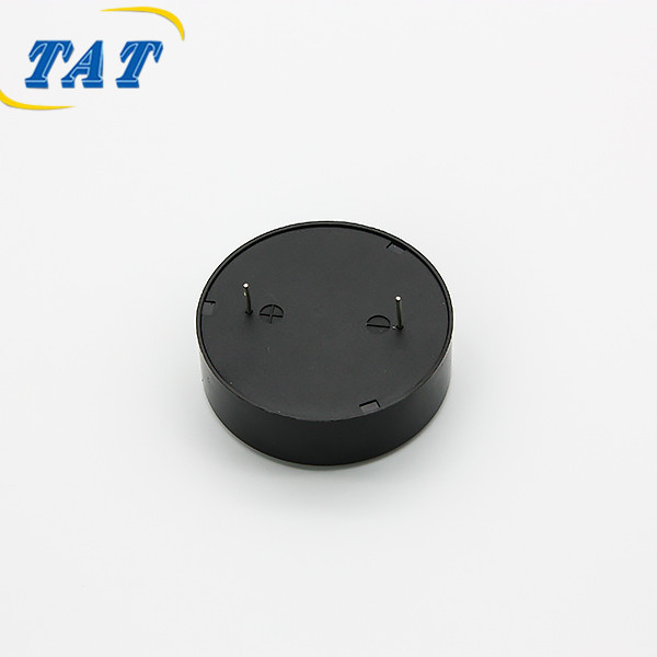
The TAT BP4414W150-10 is one of the two low-frequency parts, which makes it a useful worked example. Its resonant frequency is 1000 ± 300 Hz and it runs from 1~25 Vp-p. Rated current is Max.15mA at 1000 Hz 50% duty square wave 12 Vp-p, and sound output at 10 cm is Min.85dB under exactly that drive condition. Capacitance is 55000±30% pF at 1 kHz, the body is 44 by 14 mm on a pin mount, and it weighs approximately 11 g.
The tolerance deserves attention rather than a glance. A part specified at 1000 ± 300 Hz can resonate at 1300 Hz. That does not fail the standard by itself, because on a passive part the fundamental is set by the drive signal and not by the diaphragm. It does mean the firmware cannot simply track resonance and hope to stay conforming: at 1300 Hz you are outside the window. Choose a fixed drive frequency inside 150–1000 Hz, drive there permanently, and accept the sound pressure available at that point — a datasheet figure describes 1000 Hz, not wherever your chosen frequency lands.
The second constraint is spectral. The four loudest peaks between 300 Hz and 4000 Hz must sit within 15 dB of each other, which is a requirement about shape rather than level. A pure tone cannot satisfy it however loud it is: a sine wave has one peak, and the requirement expects four of comparable strength.
This makes the drive waveform a compliance decision, not just a design preference. A 50% duty square wave is rich in odd harmonics, and it is also the condition under which the worked example above is rated — 85 dB at 10 cm, 12 Vp-p, 1000 Hz. That overlap is not a coincidence. Square-wave drive is how a passive piezo part is expected to be used, and it is also the waveform that gives you a realistic chance of meeting the harmonic spread.
Two practical checks follow. First, take an FFT of the acoustic output rather than of the drive pin: the piezo element's own resonance decides which harmonics survive, and the enclosure reshapes them again. Second, treat the acoustic path as part of the requirement. A small cavity can notch one harmonic far below the others, and a design that measured well on the bench can miss the required spread once it sits inside the housing. If the product has a narrow sound port, measure with the port in place.
The third and fourth constraints are temporal, and no component supplier can meet them on your behalf. They follow from the priority assigned to each alarm condition, and the published characteristics table for the collateral standard gives the counts directly: ten pulses in a burst at high priority, three at medium, one or two at low. The gap between bursts is 2.5 s to 15.0 s at high priority, 2.5 s to 30.0 s at medium, and greater than 15 s or non-repeating at low. The highlights of the 60601-1-8 alarm requirements reproduce that table together with the visual counterparts — red flashing at 1.4 Hz to 2.8 Hz, yellow at 0.4 Hz to 0.8 Hz, and a steady cyan or yellow at low priority.
All of this is firmware. The part's job is narrower than it looks, but it is not nothing: it has to start and stop cleanly at the pulse rate you choose, without adding a rhythm of its own. A large diaphragm stores more energy than a small one, so when the drive is removed there is a decay tail. On a ten-pulse burst with short pulses, a long tail smears the pulses together and the burst stops sounding like a burst.
That gives you a question worth asking in writing: what does the sound do in the first milliseconds after the drive is removed? Most datasheets are silent on it.
The useful output of all four constraints is one paragraph in a purchase order. Compare two versions of the same request.
The unusable version: "Buzzer must comply with IEC 60601-1-8."
The workable version: "Part to be driven at a fixed frequency inside 150–1000 Hz, at 12 Vp-p, 50% duty square wave. Sound output at 10 cm to be at least the target figure under that drive. Supplier to state measured sound pressure at the requested drive frequency, not at resonant frequency. Supplier to state capacitance at 1 kHz and the resonant frequency distribution of the production lot."
The second version is auditable. Anyone can place a microphone at 10 cm, apply the stated drive, and disagree with a number. It also forces the right conversation, because a part rated at 85 dB at 1000 Hz has no published figure at, say, 700 Hz — and asking for one is how you find out whether the part suits the product before tooling is committed.
Two items are usually left out and both matter. Capacitance at 1 kHz tells the driver stage what it is looking into; on the worked example that figure is 55000±30% pF, a load that a microcontroller pin will not take to 25 Vp-p unaided. And the lot distribution of resonant frequency matters because a ±300 Hz window means some units sit further from your chosen drive frequency than others, with correspondingly less output. Specify only a nominal and you have specified the middle of a distribution and nothing about its edges.
When the first articles arrive, ask for five things. A sound pressure sweep from 150 Hz to 4000 Hz at your drive condition, so you can see where the part is efficient rather than where it is loudest. An FFT at your chosen frequency showing the first four harmonics. The resonance and capacitance distribution of the lot. Drive current at your condition, which is what the power budget actually pays for. And a dimensional and mounting check against the pad geometry.
What will not arrive is a compliance certificate for the buzzer, because none exists to send. The alarm-system conformity statement for a finished device comes from a test laboratory, concerns the assembled product, and belongs to the device manufacturer. A component supplier's honest contribution is measured data at a stated condition, plus a part that behaves predictably when driven.
That is the position we take on this part: the numbers on the page are stated with the drive behind them — 1000 Hz, 50% duty square wave, 12 Vp-p, at 10 cm — so a design team can reproduce them and then judge whether the frequency it actually needs lies inside the capability of the part. For a wider view of how these parameters trade against one another, the piezo buzzer range and the guide to reading a buzzer datasheet line by line cover the adjacent decisions, while the six screening gates before design freeze cover the project-level ones.
IEC 60601-1-8 constrains a signal, the buzzer constrains which signals are achievable, and the purchase order is where the two are converted into something checkable. A supplier who answers "compliant" has answered nothing. A supplier who answers with a frequency, a voltage, a duty cycle, a distance and a measured figure has given you the only thing that survives an audit.
No. The collateral standard specifies requirements and tests for alarm systems in medical electrical equipment; it does not approve components. What a buzzer supplier can provide is measured performance under a stated drive condition, and that data feeds the device manufacturer's alarm-system verification.
You can drive it there, but you are working far from resonance, so the output is much lower than the datasheet figure and there is no published number for it. If 700 Hz is where the tone must sit, select a part whose resonance is inside the 150–1000 Hz window rather than asking a 4 kHz part to operate outside its design point.
Louder helps with audibility, which is a separate question from signal structure. Meeting the frequency window, the four-harmonic spread and the burst pattern does not become easier with more output; in some enclosures a louder part simply exposes cavity resonances that distort the harmonic spread.
The device manufacturer. The conformity statement applies to the assembled medical electrical equipment and its alarm system, and it is issued on the basis of testing by a laboratory. The supplier's role in that chain is data at a defined condition plus consistency from lot to lot.


