
English 
Dedicated to global electroacoustic technology.
Views: 0 Author: Site Editor Publish Time: 2026-11-09 Origin: Site


A buzzer is almost always the last component added to a medical device and the first one nobody wants to change. By the time the enclosure exists and the firmware team is closing tickets, the sound source has already been squeezed into whatever footprint was left over. That is why so many projects discover at validation that the alarm is too quiet, or that the tone cannot be varied, or that the part sits in the one corner of the board that runs hot.
The alternative is to treat the buzzer as a decision with gates, not a line item to fill in. The six screens below are the ones worth running before design freeze. Each has an input, a pass condition and an output document. If a screen fails, it fails cheaply — on paper, not on a validated unit.
Most teams start with a part number. Start instead with a sentence: what must a specific person hear, from what position, while what else is happening?
Your customer's regulatory team will usually point at IEC 60601-1-8, the collateral standard for alarm systems in medical electrical equipment, as the frame for that sentence. Read it as a list of questions to answer, not a box to tick: which conditions need an audible signal, how those signals must be distinguishable from one another, and where the listener is expected to be standing. The IEC 60601-1-8 publication page is the reference to hand to whoever owns that answer.
The second half of this screen is human factors. Alarm design is a documented discipline in its own right, and the literature on it is blunt about one thing: a signal that is technically present but not identifiable under load does not function as an alarm. The chapter on alarm design in Handbook of Human Factors in Medical Device Design (10.1201/b10439-13) is a practical treatment of how signals get prioritised and how they get confused.
Pass condition: someone can write down the listening position, the ambient noise expected there, and how many distinct sounds the device must produce.
Output: a one-page audibility statement attached to the requirements, signed by whoever owns the risk file.
Veto: if nobody can state the listening position, stop. Every later screen inherits that ambiguity, and no datasheet can resolve it.
Now the numbers can be read — but read as conditions, not headline claims.
A passive piezo part such as the TAT BP1440S-40 is specified across an operating voltage of 1 – 20 Vp-p, with a rated current of no more than 3 mA at 4 kHz, 50% duty square wave, 5 Vp-p. Its sound output is at least 85 dB at 10 cm under those same drive conditions. Notice that the 85 dB figure has a voltage, a frequency, a duty cycle and a distance welded to it. Change any one of them and the number no longer describes your device.
So the screen is arithmetic on your own rail: what is the minimum peak-to-peak swing still available at end of battery life, at the coldest specified temperature, with the display backlight on? And what does 3 mA do to your budget when the alarm runs continuously?
Pass condition: the worst-case available drive is written down and it is at or above the condition under which the supplier measured the sound output.
Output: two lines in the power budget — worst-case Vp-p, and the current line item at the alarm duty cycle you actually use.
Veto: if worst-case drive falls below the test condition, the 85 dB figure is not your figure, whatever the datasheet says.
This is also the screen where a sourcing decision gets made. If the budget is tight, browse the passive piezo buzzer range for a lower-current part rather than hoping the loudest one fits.
This is the screen most often skipped, and it is the one that produces silent prototypes.
The BP1440S-40 is a passive part: it needs an external square-wave drive. It has no internal oscillator, so it makes no sound until something tells it to. Its resonant frequency is 4000 ± 500 Hz, and its capacitance is 15000 ± 30% pF at 1 kHz — which is the datasheet telling you, politely, that at low frequency it looks like a capacitor and not a resistor. A piezo ceramic resonator is exactly that: a mechanical resonator whose electrical behaviour is modelled as a resonant circuit, as the treatment in Piezoelectric Ceramic Resonators (10.1007/978-3-319-42481-1_3) sets out.
Practically, three questions decide the architecture:
Does an MCU pin drive it directly, or is a driver stage needed to reach the Vp-p your budget promised?
Who writes the frequency and duty cycle into firmware, and who verifies the output on a scope?
What happens at boot, in a firmware crash, or when the alarm is meant to stop?
Pass condition: one named owner for the drive signal, and a schematic block that shows where the square wave comes from.
Output: a block diagram plus the firmware ticket that implements the tone.
Veto: no owner means no sound. This is a staffing gap disguised as an electrical one.
A buzzer can fit mechanically and still be acoustically dead.
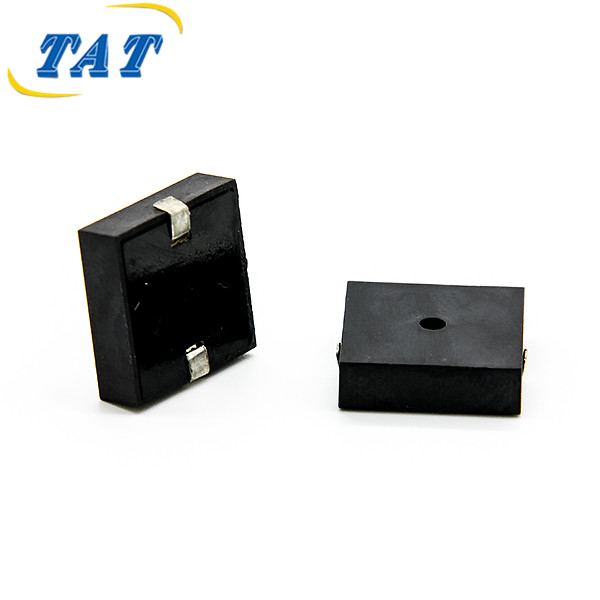
The body of this part is 14.0 × 14.0 × 4.0 mm, and 16.0 × 14.0 mm once the side metallized pads are included, with pads 0.2 mm thick and a net weight of about 0.5 g. The detail that matters most is easy to miss: the sound port is a centre hole on the top face.
That single sentence drives the mechanical design. The hole needs a clear path to the outside air. A foam gasket laid across the top face seals the port and turns a 85 dB part into a muffled thud. A conformal coating applied without masking can do the same. A housing rib that lands directly over the centre hole will do it silently, and you will only find out in the acoustic chamber.
Pass condition: the mechanical drawing shows the port, the vent path and a keep-out zone over the hole.
Output: a marked-up enclosure drawing, plus the assembly note that tells the line not to coat or gasket over the port.
Veto: if the port ends up under a sealed cover, the acoustic budget is decided by the enclosure and no component change will recover it.
Surface-mount parts get chosen for assembly reasons, and then punished by assembly.
This one mounts on SMD side metallized pads and is reflow solderable, in a black PPS housing chosen for heat resistance. Its operating temperature is -30 °C to +70 °C, with storage from -40 °C to +85 °C. Those two ranges are not interchangeable, and neither one is a statement about the board.
The screen is about local ambient, not room temperature. What sits within a couple of centimetres of the part — a regulator, a charging circuit, a lamp, a sealed battery compartment? A device developed on a comfortable bench can still present still air far hotter than the room at that corner after an hour of operation, and a +70 °C ceiling leaves very little headroom for a hot spot.
Pass condition: someone has estimated local ambient at the buzzer location in the worst operating mode, and it sits inside -30 °C to +70 °C with margin.
Output: a thermal note with the estimate and its assumptions, owned by whoever owns the layout.
Veto: if local ambient crosses +70 °C in normal use, change the position or change the part before freeze, not after.
Teams comparing package styles usually reach this screen with an open question about assembly trade-offs; the notes on SMD buzzers cover the practical differences, and the full buzzer range is the place to look if the footprint has to change.
The last screen is not technical. It is about what you can hand to an auditor, a customer or your own future self.
For each of the five screens above, there should now be a document: the audibility statement, the energy calculation, the drive ownership, the mechanical vent path, the thermal estimate. If any of them lives only in someone's head, the freeze is not real.
Then ask the supplier for the measurement conditions behind the sound figure, in writing. For this part that means at least 85 dB at 10 cm, measured at 4 kHz, 50% duty square wave, 5 Vp-p. If a quotation offers a sound level without those qualifiers, the number is marketing rather than specification. The same discipline applies when reading any supplier document, which is why the checklist in how to read a buzzer datasheet is worth running over every candidate.
Pass condition: six documents exist and are attached to the BOM line.
Output: an acceptance checklist that travels with the part number.
Veto: if you cannot state the conditions behind your own sound specification, you cannot verify it later.
None of these six screens takes long, and none of them requires a prototype. They are cheap precisely because they happen on paper, before a layout is locked and before a validation run is scheduled.
The pattern behind them is the same in every case: a component number is not a decision. A voltage that exists at worst case is a decision. An owner for the drive signal is a decision. A vent path over the sound port is a decision. A measured condition behind a decibel figure is a decision.
If your project is choosing between drive technologies rather than checking a single part, the comparison in choosing an alarm buzzer is the natural next read. If it is already committed to a passive piezo, run the six screens and freeze with evidence.
Sometimes, but the pin must be able to supply the peak-to-peak swing your sound specification assumes. The BP1440S-40 is rated across 1 – 20 Vp-p, and its sound output is quoted at 5 Vp-p. If the pin cannot reach that swing, a driver stage is the difference between meeting the specification and missing it.
Because the part is a resonator, not a resistor. The 15000 ± 30% pF at 1 kHz figure describes how the ceramic behaves electrically at a reference frequency, which is what a drive circuit has to work with. The resonant frequency, 4000 ± 500 Hz, describes where it is mechanically efficient.
No. A decibel figure is meaningless without its distance, drive voltage, frequency and duty cycle. At least 85 dB at 10 cm at 4 kHz, 50% duty square wave, 5 Vp-p describes a measurement; “85 dB” on its own describes a hope.
The acoustic path, not the component. A sound port blocked by a gasket, a coating, or a housing rib is far more common than a part that underperforms its own specification — and it is invisible until the device is assembled.


