
English 
Dedicated to global electroacoustic technology.
Views: 0 Author: Site Editor Publish Time: 2026-11-07 Origin: Site


The electret condenser microphone vs MEMS microphone decision is usually framed as old against new. That framing is the first thing to discard. Both are capacitor microphones — a diaphragm moving against a fixed backplate, changing capacitance, driving a buffer — and both remain in volume production for products shipping this year. What separates them is not generation but physics of construction, and that physics decides which processes your assembly line can run and which supplier you can buy from.
This comparison is written from the perspective of a company that manufactures electret condenser microphones, so the ECM side is grounded in published specifications you can verify page by page. The MEMS side is described at the level of principle and process, because the differences that matter to an OEM design are process differences, not catalogue numbers. Where a figure appears below, it comes from a specification table; where a claim is general to the category, it is labelled as typical rather than quoted as a specification.
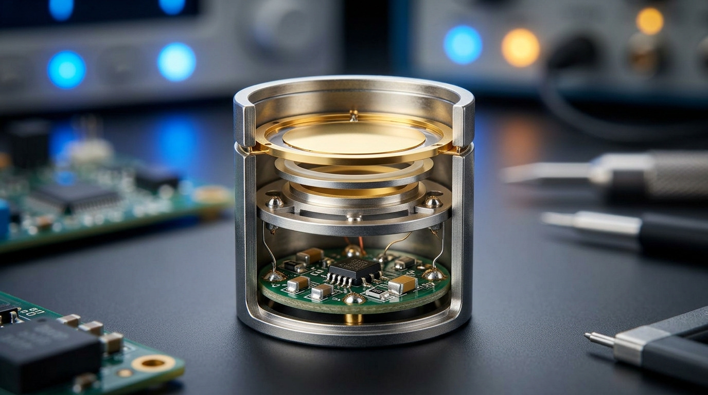
An electret condenser microphone is a discrete assembly. A polymer electret film holds a permanent charge, so the capsule needs no polarising supply — only a small bias resistor and a buffer, historically a junction FET built into the capsule. The parts are stamped, wound, mounted and sealed mechanically.
A MEMS microphone is a semiconductor device. The diaphragm and backplate are etched in silicon, the buffer is integrated on the same die, and the output is either analog or digital. Because it is built on a wafer, it is packaged like other semiconductors: tape and reel, pick and place, reflow.
That single difference — discrete assembly versus wafer fabrication — propagates into all seven differences below. When a design decision seems arbitrary, trace it back and it usually lands on this one.
Dimension | Electret condenser (ECM) | MEMS |
|---|---|---|
Construction | Discrete capsule, polymer electret film, separate buffer | Silicon die, integrated buffer |
Polarising supply | Not required (electret holds charge) | Not required (charge pump on die) |
Bias network | Bias resistor + supply decoupling | Supply decoupling, often a regulated rail |
Output | Analog, single-ended | Analog or digital (PDM / I2S) |
Assembly | Through-hole pins, solder pads, or wire leads | Reflow, tape and reel |
Unit-to-unit spread | Selected into sensitivity bins | Tighter out of the wafer, per datasheet |
Smallest practical size | Millimetres of diameter, ~1.5 mm thickness | Smaller, and square rather than round |
Both categories need a bias network, and the difference is what that network has to do.
An ECM needs a resistor from supply to the capsule's drain and a coupling capacitor on the output. The supply does not have to be precise, because the electret charge — not the supply — sets the operating point. The consequence is visible in the specifications: the TAT-EM6027 states a standard operating voltage of 2 V and a sensitivity reduction within 3 dB at 1.5 V. That line is the useful one. It says a 25 percent drop in supply costs you at most 3 dB of output — which is why ECM designs tolerate a sagging rail far better than their supply tolerance suggests.
A MEMS microphone integrates a charge pump, which means it generates its own internal high voltage from the supply. That pump is a switching circuit, so the supply has to be quiet and stable, and the datasheet will usually specify a maximum ripple. In practice most MEMS designs add a dedicated low-dropout regulator that an ECM design does not need. That regulator is a component, a placement, a decoupling capacitor and a line on the BOM — a real cost that does not appear in the microphone's unit price.
The practical rule: if your rail is already regulated and quiet, MEMS bias costs nothing extra. If your rail is a battery that sags from 3.6 V to 2.8 V over discharge, the ECM's tolerance is a design feature you should price in before switching.
This is where procurement and engineering most often talk past each other.
ECM sensitivity is not a single number — it is a tolerance band, and parts are sorted into bins after production. The published options on the TAT-EM4015 are −46 ±3 dB, −44 ±3 dB and −42 ±3 dB at 1 kHz with 0 dB referenced to 1 V/Pa. Three bins, each ±3 dB wide. Read that carefully: you choose a bin, and inside the bin there is still a 6 dB span from lowest to highest.
For a single microphone in a product, a 6 dB spread is invisible. For a product with two microphones — a headset, a stereo pair, an array — it is the difference between matched channels and a customer complaint. That is why ECM-based multi-microphone designs either specify a tighter bin, buy matched pairs, or add gain calibration in firmware.
MEMS parts are specified with a tolerance too, and the wafer process generally delivers a tighter distribution, which is one legitimate reason MEMS won in phone handsets where dozens of units ship per device. But "tighter" is a relative statement, not an absolute one. The engineering task is the same in both cases: read the tolerance band, multiply it by the number of microphones in the product, and decide whether firmware calibration is cheaper than a tighter part.
MEMS capsules are typically a few millimetres square and around a millimetre tall — small, and square. ECM capsules are round, because the diaphragm is a stretched circular film clamped in a metal can.
Round versus square sounds cosmetic. It is not. A square package tiles: you can place two of them side by side with a known gap and a predictable acoustic centre spacing, which is exactly what an array needs. A round capsule leaves dead space at every corner, and the acoustic port is at the centre of a circle, so spacing is set by diameter plus clearance.
The size range is real but narrower than marketing suggests. On this site the two documented ECM sizes are Φ6.0 ± 0.2 × 2.7 ± 0.15 mm for the 6027 series and Φ4.0 ± 0.2 × 1.5 ± 0.1 mm for the 4015 series, the latter at ≤ 0.2 g. A 4 × 1.5 mm capsule is small enough for earbuds and wearables — the segment where ECM is supposedly finished. It is not finished there; it is simply competing on a different axis.
The honest framing: MEMS wins when the constraint is "smallest possible and square", ECM wins when the constraint is "small enough, and cheaper, and I can solder it".
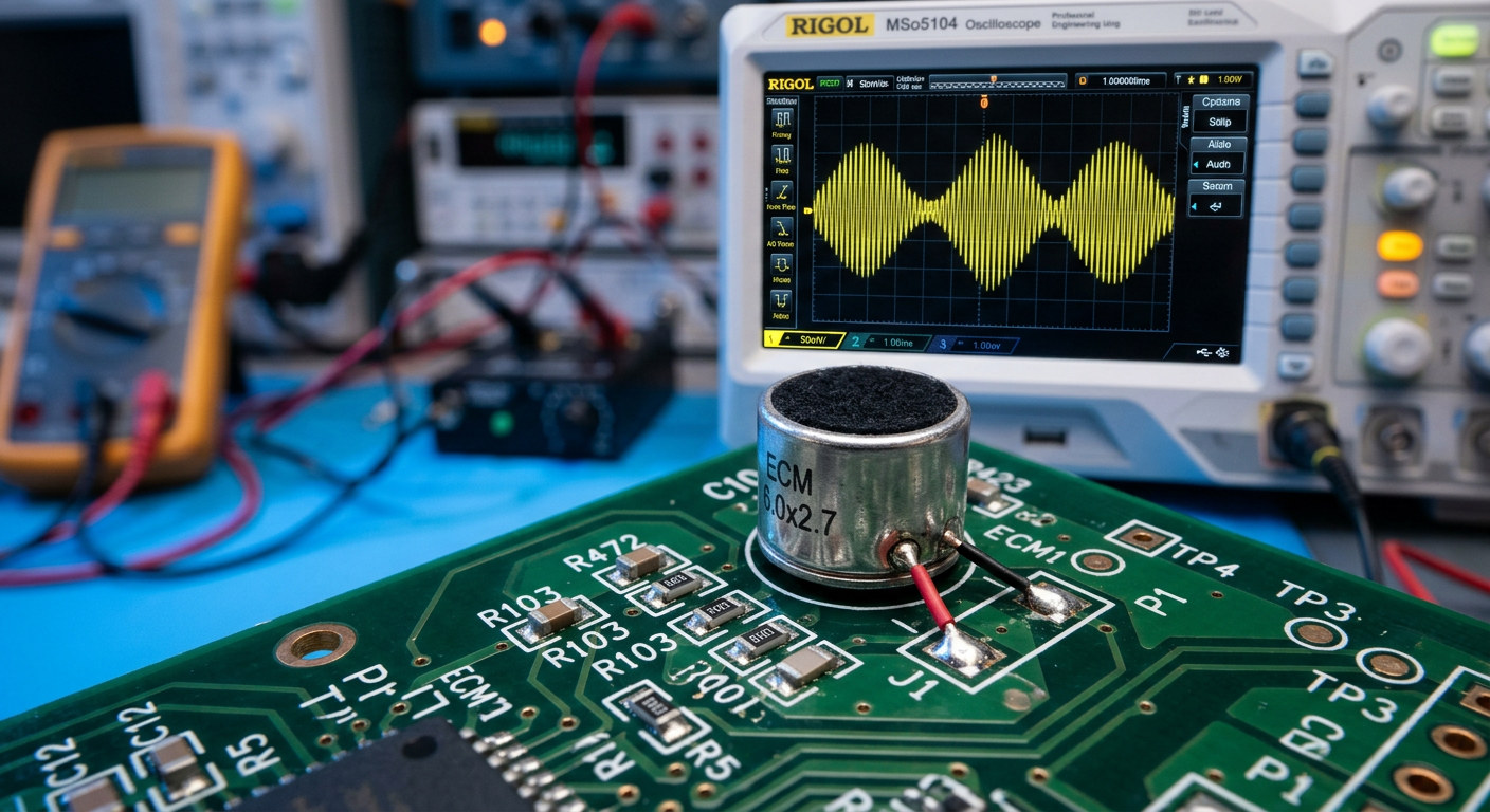
This is the difference that decides your assembly line, and it is the one most often decided by accident.
MEMS microphones are designed for reflow. Tape and reel, pick and place, oven with the rest of the board. The package is engineered for it, including the acoustic port, which is covered by a temporary protective film that the assembly process removes or that bursts at a defined pressure.
ECM capsules are mechanical assemblies with a polymer film under tension. Their termination options tell you what process they were designed around. Look at the published options rather than assuming:
Part | Termination options published |
|---|---|
TAT-EM6027 | M6027P through-hole pins / M6027A solder pads |
TAT-EM4015 | M4015A SMD pads / M4015B pin-hole / M4015P through-hole pins / wire-lead |
Four terminations on one 4 mm capsule is not indecision — it is a supplier acknowledging that its customers run four different processes. Wire-lead parts exist for assemblies that are hand-built or potted. Through-hole pins exist for wave-soldered boards. Solder pads exist for reflow with a stencil. None of those is a legacy compromise; they are the reason ECM still ships in products whose boards are not all-SMT.
The practical question is not "can an ECM go through reflow" but "which termination do I need, and does my process actually support it". If the answer is hand soldering, remember that a soldering iron next to a 1.5 mm capsule is a thermal event, and the published sensitivity reduction figures apply to supply voltage, not to a 350 °C tip.
Wireless products have made this difference more valuable than it used to be.
The TAT-EM6027 is specified as a shielded electret condenser microphone with a metal shield described as anti-2.4G/Wi-Fi interference. That is a structural advantage: the metal can is the shield, and it surrounds the capsule rather than sitting beside it. In a product with a 2.4 GHz radio centimetres from the microphone — TWS earbuds, a wireless headset, a 2.4G lavalier — that shield is doing work that a MEMS solution has to solve at board level.
MEMS microphones are not defenceless here. Differential output, ground guarding and layout discipline all help, and a well-designed MEMS layout is quiet. But the shielding is a board-level activity with board-level cost, and it has to be re-verified every time the layout changes.
For a design team with limited RF test capability, an ECM with a metal can converts a layout problem into a part selection. That is a legitimate engineering trade, not a shortcut.
Signal-to-noise ratio is the number to compare, and both categories publish it.
On this site the 6027 series is specified at > 58 dB and the 4015 series at > 56 dB, both measured at 1 kHz with 0 dB referenced to 1 V/Pa. The EM6050P-40dB publishes 55 dB at 1 kHz, S.P.L. = 1 Pa, A-weighted, alongside a maximum impedance of 2.2 kΩ, a minimum current of 50 μA and a 4.5 V operating voltage range.
Three of the capsules in this range publish a usable table. Side by side, the differences between a 6 mm and a 4 mm capsule are the ones that decide the application:
Parameter | TAT-EM6027 | TAT-EM4015 | EM6050P-40dB |
|---|---|---|---|
Size | Φ6.0 ± 0.2 × 2.7 ± 0.15 mm | Φ4.0 ± 0.2 × 1.5 ± 0.1 mm | 6.0 × 5.0 mm series |
Directivity | Omnidirectional | Omnidirectional | Omni-directional |
Standard operating voltage | 2 V | 2 V | 4.5 V range |
Current consumption | Max. 0.5 mA | Max. 0.5 mA | Min 50 μA |
Sensitivity (1 kHz, 0 dB = 1 V/Pa) | −46 / −44 / −42 ±3 dB | −46 / −44 / −42 ±3 dB | Not quoted here — see note |
Sensitivity reduction | Within 3 dB at 1.5 V | Within 3 dB at 1.5 V | — |
S/N ratio | > 58 dB | > 56 dB | 55 dB (A-weighted) |
Termination | Through-hole pins / solder pads | SMD pads / pin-hole / pins / wire-lead | — |
Waterproof variant | — | Available (wire-lead version) | — |
One note on the third column. The EM6050P-40dB page publishes a sensitivity figure that does not agree with the sensitivity embedded in its own model name, so that number is deliberately left out of this comparison. It is a good reminder that a specification table and a part number can disagree, and that the table is not always the more recent of the two — verify with the supplier before you design around either.
Those numbers place ECMs in a specific band: mid-fifties to high-fifties for standard capsules. Larger capsules with more diaphragm area do better, which is why the 6 mm part beats the 4 mm part on this metric. MEMS parts are typically specified in a similar or slightly higher band, and the newest ones push higher still — but the audible difference in a product is usually set by the acoustic design around the port, not by the last 3 dB on the datasheet.
The low-supply behaviour is more interesting than the noise figure. A 2 V standard operating voltage with sensitivity reduction within 3 dB at 1.5 V means an ECM keeps working deep into battery discharge. A MEMS part with an internal charge pump has a minimum supply below which the pump stops regulating, and output falls off a cliff rather than a slope. If your product runs on a coin cell or a single lithium cell without a boost converter, plot both curves before deciding.
Unit price is the wrong comparison, for a reason specific to this category.
An ECM is a mechanical assembly made with stamping, winding and sealing equipment. Tooling is modest, minimum order quantities are usually negotiable, and a new sensitivity bin or a different wire length is often a configuration change rather than a new part. An EM9767 or an M4520W is the kind of part a mid-volume OEM can specify without a semiconductor design cycle.
A MEMS microphone is a wafer-fab product with the economics that implies: long lead times, allocation risk, and a supplier base measured in a handful of companies. The part itself can be inexpensive at volume, but the flexibility is different. Changing a sensitivity bin in a MEMS part means changing part numbers within a fixed catalogue. Changing it in an ECM often means asking the factory.
There is a second-order cost that gets missed. A MEMS design usually adds a regulator, more decoupling and layout care around the port. An ECM design adds a bias resistor and a coupling capacitor, and possibly a hand-soldering or wave-soldering step. Whichever extra work your line is already set up to do is the cheaper one — and that is a factory question, not a datasheet question.
The decision collapses into a short list once the process questions are answered first:
If this is your constraint | The usual answer |
|---|---|
Everything must go through reflow, no exceptions | MEMS |
Smallest possible footprint, square for tiling | MEMS |
Digital output required (PDM / I2S) | MEMS |
Hundreds of thousands of units per year, one design | MEMS |
Unregulated or sagging battery rail | ECM (check the low-voltage curve) |
Strong 2.4 GHz / Wi-Fi field near the microphone | ECM with a metal shield |
Cost-sensitive, mid volume, mixed assembly | ECM |
Wave solder or hand assembly already in the line | ECM with pins or wire leads |
Product needs a wire-lead or potted assembly | ECM |
Long product life with a stable BOM | ECM (configuration changes are easier) |
Notice how many rows are process rows. That is the pattern: the acoustic performance of the two categories overlaps heavily, and the decision is usually made by manufacturing and procurement, then justified acoustically afterwards.
Four errors show up repeatedly when teams switch between the two categories:
Treating sensitivity as a single number. A part specified at −44 dB is a bin, and the bin has width. Multiply that width by the number of microphones before deciding it does not matter.
Forgetting that an ECM needs a bias resistor and a coupling capacitor. The BOM comparison that omits them is not a comparison. Conversely, a MEMS comparison that omits the regulator and its decoupling is equally incomplete.
Reading a supply tolerance as an acoustic specification. The 3 dB figure at reduced voltage is an output change, not a distortion figure. Distortion at low supply has to be measured.
Assuming a quoted sensitivity is a measured value for your board. It is a capsule measurement at a stated frequency and reference. The port, the gasket and the cavity in front of the capsule will change what your product delivers, sometimes by more than the difference between the two technologies.
The electret condenser microphone vs MEMS microphone choice is not a question of which technology is current. It is a question of which construction fits your assembly process, your supply chain and your acoustic geometry. ECM brings a discrete capsule that tolerates unregulated rails, accepts a metal shield as part of its construction, and terminates in pins, pads or wire leads depending on how your line is built. MEMS brings wafer consistency, reflow compatibility and digital output, at the cost of a regulated supply and a narrower supplier base.
Decide the process questions first — reflow or not, regulated rail or not, shielded or not, mid volume or high volume — and the part category follows. Only then compare noise figures, because by that point the contenders will already be in the same band.
A: Some can, in a specific configuration. The signal is the termination options the supplier publishes: a part offered only with through-hole pins or wire leads was designed around wave or hand soldering, while a part offered with SMD pads is intended for a stencil and an oven. Ask for the reflow profile the part is rated for, and treat "we have used it in reflow before" without a profile as unverified. A capsule is a tensioned polymer film in a metal can; heat tolerance is a property of that assembly, not of the microphone category.
A: No — the larger the negative number, the lower the sensitivity, so −42 dB is the more sensitive bin and −46 dB is the quieter one. The convention is easy to invert under time pressure, which is why it is worth writing the ordering into the drawing note rather than leaving it in a datasheet reference. All three options are quoted at 1 kHz with 0 dB referenced to 1 V/Pa, so they are directly comparable to each other.
A: Because the parts come off the line with a spread, and sorting is cheaper than tightening the process. Offering three bins lets a design choose where to sit: a single-microphone product can take the widest bin, while a two-microphone product that needs matched channels picks a tighter bin or adds calibration. When you compare two ECM parts, compare the bin width as well as the nominal value — a part with a ±2 dB band and a part with a ±3 dB band are not interchangeable in a stereo design even when their nominal figures match.
A: Usually not. The bias resistor sets the operating point and the electret charge holds it, so a supply that drifts by a few hundred millivolts costs little output — the published figures for this range are a sensitivity reduction within 3 dB at 1.5 V against a 2 V standard. What the ECM does need is a clean supply, because the bias resistor passes supply noise straight into the capsule. A MEMS part needs a stable supply for a different reason: its internal charge pump is a switching circuit and has to regulate. In both cases the requirement is decoupling close to the part, not necessarily a regulator.
A: Signal-to-noise ratio is the number to compare, and it is published for both categories. The capsules in this range specify above 58 dB for the 6 mm series and above 56 dB for the 4 mm series; MEMS parts are typically specified in a similar band. In a finished product the audible noise floor is usually set by the acoustic path — the port diameter, the gasket seal, the cavity volume in front of the diaphragm — long before it is set by 3 dB of capsule self-noise. Fix the acoustic design first, then choose the capsule.


