
English 
Dedicated to global electroacoustic technology.
Views: 0 Author: Site Editor Publish Time: 2026-11-15 Origin: Site


A 3.3 V microcontroller pin and a 3 V buzzer look like a matched pair on paper. The part is rated for 3 V, the pin delivers 3.3 V, and the gap between them seems small enough to ignore. That reasoning is how prototypes end up with a pin that runs warm, a buzzer that sounds thin, or a board that resets every time the alert fires.
The gap that matters is not the 0.3 V. It is the current. Four decisions determine whether a GPIO-driven buzzer works: whether the pin can supply the coil, which switch sits between them, what resistor feeds that switch, and when a diode is mandatory.
The TAT BM4020S-0340-17 is a useful case because its published numbers are explicit for a part this small. Rated voltage is 3 VDC, operating voltage is 2~5VDC, resonant frequency is 4000Hz, and sound pressure level is 80dB. A 3.3 V rail sits comfortably inside the 2~5VDC window, which is exactly why designers assume a direct connection is acceptable.
The same table gives the number that settles the question: coil resistance is 17±3Ω. A magnetic buzzer is a coil around a diaphragm, and a coil of that resistance connected across 3.3 V would draw roughly 194 mA in steady state. No general-purpose GPIO pin sources that. The pin's own rating is usually an order of magnitude lower, and even a generously rated pin will not hold its output voltage under that load, so the buzzer sees less than the rail while the microcontroller faces a brownout risk on every alert.
That is the first thing to internalise: the operating voltage tells you what the part needs, and the coil resistance tells you what the driving circuit must survive.
Seventeen ohms is a DC measurement. It is the right number for calculating worst-case current if the coil were held across the supply continuously, and the right number for checking whether a driver can survive a shorted load. It is not the rated operating current, and it should not be used to estimate average battery draw.
A magnetic buzzer is driven by an alternating waveform, not by DC. The coil sees a square wave, the diaphragm moves at the drive frequency, and the average current depends on the drive waveform and on the coil's impedance at that frequency, which is higher than its DC resistance. The published table does not state a rated current, so the honest answer to "how much does this buzzer draw" is that you measure it in your own circuit. Use 17±3Ω to size the switch, and use a current probe to size the battery.
Once the GPIO is out of the current path, something else has to carry the coil. Low-side switching with an N-channel device is the normal arrangement: the buzzer's positive terminal goes to the rail, its negative terminal goes to the switch, and the switch goes to ground. The GPIO drives the control terminal and never touches the coil.
A bipolar NPN transistor is the cheapest option and is adequate here. It needs a base current, and it introduces a saturation voltage between collector and emitter while it is on. That saturation voltage subtracts from the rail, so the buzzer sees slightly less than 3.3 V. With an operating window that starts at 2 V there is room for that loss, which is one reason the 2~5VDC rating is more forgiving than it first appears.
A logic-level N-channel MOSFET avoids the base current almost entirely and usually has lower on-resistance. The trade-off is cost, plus the need to confirm the part is specified for a 3.3 V gate drive rather than a 10 V one, because a MOSFET characterised only at higher gate voltages may never fully enhance at 3.3 V and will behave like a resistor instead of a switch. If the design already uses a logic-level FET, keep it. If not, an NPN and one resistor will do.
The base resistor converts a voltage into a current, and the current it must produce is set by the collector current and the transistor's gain. The arithmetic is simple enough to finish before the board is ordered.
Decide the collector current the transistor must carry. This is the coil current, best measured, but for sizing the switch a conservative figure derived from the DC resistance is acceptable because it overstates rather than understates the requirement. Divide by the DC current gain to get the base current. Subtract the base-emitter drop from the GPIO voltage, and divide by the base current.
Take a collector current of 100 mA and a transistor with a gain of 100. The base current that barely supports that is 1 mA. Assume a base-emitter drop of 0.7 V, so the resistor sees 2.6 V. Dividing 2.6 V by 1 mA gives 2.6 kΩ.
Do not use 2.6 kΩ. A transistor operated at exactly the calculated base current sits on the edge of saturation, where small changes in gain, temperature, or batch move it into the linear region, and a transistor in the linear region dissipates power and runs hot. Standard practice is two to five times the calculated base current, which brings the resistor to between 1 kΩ and 500 Ω. A 1 kΩ resistor delivering 2.6 mA is comfortable for this example.
Two cautions belong with that number. The gain quoted on a datasheet is a minimum at a specified collector current, and it falls at low temperature, so sizing against a typical gain rather than the minimum is how marginal designs happen. And the GPIO has its own source limit; if the resistor asks for more current than the pin can deliver, the pin voltage sags and the base current is not what the arithmetic promised.
When a transistor turns off an inductive load, the coil's current cannot stop instantly. The collapsing field produces a voltage at the collector that can be many times the supply, and it will destroy a transistor that is not protected. A diode across the coil, cathode to the positive rail and anode to the collector, gives that current a path to circulate until it decays.
Three selection points matter. The reverse voltage rating must exceed the supply with margin, the forward current rating must handle the coil current at least momentarily, and a fast-recovery type is preferable to a slow rectifier because the current transfers to the diode quickly. A small signal diode is adequate for a buzzer of this size; the mistake to avoid is omitting it because the part is small.
The diode is not universal across buzzer families. A piezoelectric buzzer is a capacitor, not a coil, so it stores energy in an electric field and does not produce the same inductive kick. Designs that replace a magnetic part with a piezo and keep the diode are merely carrying a component they no longer need. Designs that replace a piezo with a magnetic part and drop the diode are the ones that fail in the field. The SMD buzzer range contains both families, so confirm the family of the specific part before the schematic is frozen.
A magnetic buzzer has a resonant frequency, and for this part it is 4000Hz. Drive it there and the diaphragm works with the acoustic system rather than against it, which is where the published 80dB comes from. Drive it well away from that point and the output falls, sometimes far enough to turn an audible alert into a click.
The consequence is that a passive magnetic buzzer needs a continuous square wave at the resonant frequency, produced by a hardware timer rather than a software loop. A loop that toggles a pin is at the mercy of interrupt latency, and the resulting jitter spreads energy away from the resonance. A hardware PWM channel with a 50 percent duty cycle is the clean solution, and the transistor inverts it, which is harmless for an AC-driven load.
A passive part is silent unless driven, so the firmware must start the waveform and stop it when the alert ends.
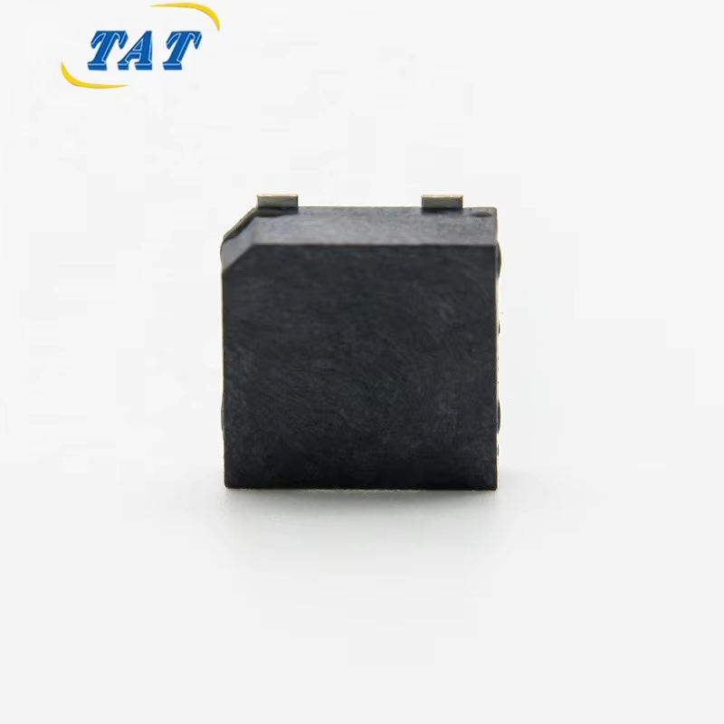
The BM4020S-0340-17 is a surface-mount part with a 4.0±0.3mm by 2.0±0.3mm outline and a height of 2.2mm, marked with a polarity indicator and a sound port. Both markings matter during layout. The polarity mark tells the assembly house which orientation is correct, and the sound port tells you where not to place anything that could block it.
Three layout habits prevent most post-reflow problems. Keep the sound port clear of tall components and conformal coating, because a coated port turns a loud part into a quiet one and the failure is easily misdiagnosed as a bad batch. Keep the switching loop — transistor, buzzer, diode — physically small, because that loop is where the fast current edges radiate. And keep the buzzer away from microphone capsules and their traces; a part producing 80dB at close range will couple into a high-impedance microphone node regardless of acoustic sealing.
For assembly, the part is intended for standard SMT reflow, and its storage range of -40℃~+85℃ is the number to use when deciding whether a reel can sit in an unconditioned store. Its operating range of -20℃~+70℃ is the number to compare against the enclosure's internal temperature, not the ambient of the room the product sits in.
Verification starts at the collector. With the buzzer sounding, an oscilloscope on the collector shows the saturation voltage while the device is on and the clamp voltage while it is off. A saturation voltage higher than expected means insufficient base drive and a transistor lingering in the linear region, which is a resistor problem rather than a buzzer problem. A clamp voltage well above the rail with the diode fitted points to orientation or placement.
Current is the second measurement. A probe or a shunt in the ground return gives the average and peak figures the battery budget needs, and those are the figures to record, because the table publishes no rated current.
Sound is the third, and it is the measurement most often done badly. A phone application is not an instrument; it has its own frequency response and automatic gain. A sound level meter built to the instrument requirements of IEC 61672-1 is the appropriate tool, and the NIST Physical Measurement Laboratory publishes reference material that makes traceability meaningful. Whatever instrument is used, distance and mounting conditions belong in the test record, because a level quoted without them cannot be compared with anything, including the supplier's own figure.
The last check catches the most field failures: run the alert repeatedly at the temperature extremes of the operating range and confirm that both the sound and the saturation voltage hold up. A buzzer that works at room temperature and fades at the cold end is a margin problem, and -20℃~+70℃ tells you where to test.
Driving a buzzer from a 3.3 V GPIO is a four-part decision. Confirm whether the coil can be driven directly, which for a 17±3Ω magnetic part it cannot. Choose a switch a 3.3 V pin can actually turn on. Size the base resistor against the minimum gain, then add margin so the transistor saturates rather than lingering in the linear region. Fit a diode if the part is magnetic, and skip it if the part is piezo. Sibling parts such as the BM5020S follow the same rules with different coil values.
None of that requires an unusual component. It requires reading the operating voltage and the coil resistance as two separate statements, and treating the GPIO as a signal rather than a supply.
Can I connect the buzzer straight to the GPIO if I add a series resistor? A series resistor limits current but does not fix the problem, because the voltage arriving at the buzzer depends on the resistor and the coil together, and the sound output falls as that voltage falls. The transistor exists so the buzzer sees close to the full rail regardless of what the pin can supply.
Why does my buzzer sound quieter than the datasheet figure? Three common causes: the drive frequency is off resonance, the transistor is not fully saturated so the coil sees less than the rail, or the sound port is obstructed by coating or a nearby component. The published 80dB also comes with test conditions the product page does not restate, so compare like with like before blaming the part.
Do I need the diode if I use a MOSFET instead of a transistor? Yes. The diode protects against the coil's collapse, not against the switch type. A MOSFET has a body diode, but it is not connected across the load and does not perform the same function.


