
English 
Dedicated to global electroacoustic technology.
Views: 0 Author: Site Editor Publish Time: 2026-08-10 Origin: Site


Hardware engineers face a relentless core challenge today. You must balance adequate acoustic output against increasingly stringent PCB space constraints and automated assembly demands. Devices continue to shrink. This leaves little room for traditional bulky audio components. Through-hole transducers often disrupt standard Surface Mount Technology (SMT) lines. They force secondary hand-soldering stages and slow down entire production runs.
Enter the SMD Buzzer. This surface-mount electro-acoustic transducer is engineered specifically for high-speed pick-and-place manufacturing. These low-profile components solve the miniaturization puzzle while maintaining reliable sound pressure levels. They adapt perfectly to tight enclosures and dense board layouts.
This article provides hardware designers and procurement teams an objective evaluation framework. You will learn to properly evaluate, select, and implement surface-mount buzzers for volume production. We cover everything from structural anatomy and driving principles to thermal profiling during lead-free reflow.
Assembly Efficiency: SMD buzzers eliminate manual through-hole soldering, integrating seamlessly into standard SMT (Surface Mount Technology) pick-and-place lines.
Space Optimization: Their low-profile footprint reduces Z-axis height, making them critical for compact IoT, medical, and consumer electronics.
Technology Trade-offs: Selecting between magnetic and piezoelectric SMD variants requires balancing operating voltage, current consumption, and target SPL (Sound Pressure Level).
Thermal Realities: Successful implementation depends on strict adherence to lead-free reflow soldering temperature profiles to prevent acoustic diaphragm degradation.
Understanding component structure helps you optimize board layouts. A surface-mount buzzer relies on highly specialized materials. It must endure extreme temperatures while delivering consistent acoustic performance.
The physical form factor relies on three main components. First, manufacturers use Liquid Crystal Polymer (LCP) or Polyphenylene Sulfide (PPS) for the outer housing. These high-temperature plastics resist melting during oven exposure. Inside the housing sits the sound-generating mechanism. This is either an electromagnetic coil structure or a piezoelectric ceramic element. Finally, the unit connects to the board via flat terminal pads located on the bottom. These flush pads align perfectly with printed solder paste.
Engineers must choose between two distinct operational architectures. Your choice dictates the required microcontroller unit (MCU) resources.
Active Configurations: These units feature a built-in oscillating circuit. They require only a steady DC voltage to operate. Once powered, they emit a continuous tone at a fixed frequency. They simplify software development greatly. You only need a simple GPIO pin toggle to activate them.
Passive Configurations: These lack internal drive circuitry. They require an external PWM (Pulse Width Modulation) signal from your MCU. This demands more software overhead. However, it allows you to generate variable tones, multi-frequency melodies, and complex alert sequences.
Component packaging is critical for high-speed manufacturing lines. Suppliers ship these transducers in standard Tape and Reel formats. A carrier tape holds each unit securely in a precisely molded pocket. A thin cover tape seals the pockets. The pick-and-place machine's vacuum nozzle relies on a flat top surface to lift the component. This automated approach ensures rapid placement and reduces human handling errors.
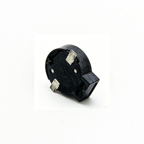
Transitioning from traditional through-hole components to surface-mount equivalents transforms your entire production strategy. It affects physical dimensions and mechanical reliability alike.
Through-hole (DIP) buzzers disrupt modern PCB assembly. Standard SMT lines populate top and bottom board layers rapidly. Inserting a through-hole part requires a secondary process. Factories must use selective wave soldering or manual hand-soldering. Both methods introduce bottlenecks. An SMD Buzzer eliminates these secondary stages entirely. It reflows alongside your resistors, capacitors, and ICs. This integration accelerates manufacturing throughput dramatically.
Through-Hole vs. Surface-Mount Processing
Process Variable | Through-Hole (DIP) Buzzers | Surface-Mount (SMD) Buzzers |
|---|---|---|
Placement Method | Manual insertion or specialized radial insertion equipment | Standard high-speed automated pick-and-place |
Soldering Stage | Wave soldering or manual hand-soldering | Standard convection reflow oven |
PCB Footprint | Requires drilled holes through all board layers | Occupies only surface-level copper pads |
Modern product designs demand extreme miniaturization. Wearable electronics, medical monitors, and smart home sensors leave very little room for bulky parts. Through-hole components demand thick Z-axis clearance. Surface-mount variants feature a highly compressed, flat geometry. You can place them on densely populated, multi-layer PCBs. This low-profile nature helps industrial designers shrink the final device enclosure significantly.
Mechanical stability matters for devices subjected to drops or motor vibrations. Through-hole pins can act as tiny levers during a drop shock. This leverage stresses the solder joint. Surface-mount pads offer robust mechanical adhesion. The large, flat solder surface area distributes sheer forces evenly. This prevents contact detachment during continuous operational vibration. It keeps the acoustic connection secure over the product's lifespan.
Selecting the right acoustic technology dictates your power budget and sound profile. You must align the component's internal physics with your application's specific constraints.
Magnetic variants operate using an internal electromagnetic coil. Applying voltage generates a magnetic field. This field pulls a metal diaphragm down. Releasing the voltage allows the diaphragm to snap back. Repeating this cycle rapidly generates sound waves.
Best for: Low-voltage logic applications. They operate comfortably between 1.5V and 5V. This makes them perfect for standard 3.3V MCU rails.
Trade-off: They consume much more current. A typical unit draws between 20mA and 100mA. This heavy draw can drain small coin-cell batteries quickly.
Output Tone: The heavier internal diaphragm naturally creates a lower resonant frequency (often around 2.7kHz). This produces a "warmer," more pleasant audio tone.
Piezoelectric types use a ceramic disc bonded to a brass or alloy plate. Applying voltage causes the ceramic to physically deform and bend. Alternating the voltage vibrates the plate, pushing air to create sound.
Best for: Low-power and battery-operated equipment. They fit perfectly into wireless IoT sensors and portable medical gear.
Trade-off: They require a higher driving voltage. To achieve maximum volume, you often need 3V to 20V+. However, their current draw is minimal, usually staying well under 5mA.
Output Tone: The stiff ceramic structure resonates at a higher frequency (often 4kHz or above). This delivers sharp, piercing alerts. High frequencies cut through noisy industrial environments effectively.
Acoustic Technology Selection Chart
Parameter | Magnetic SMD | Piezoelectric SMD |
|---|---|---|
Driving Voltage Range | 1.5V to 5V (Low) | 3V to 20V+ (High) |
Current Consumption | 20mA to 100mA (High) | Under 5mA (Low) |
Resonant Frequency | ~2.0kHz to 3.0kHz | ~4.0kHz to 6.0kHz |
Perceived Audio Profile | Warmer, lower pitch | Sharp, piercing alert |
Ideal Application | USB-powered devices, appliances | Battery-operated IoT, wearables |
To finalize your decision, frame the choice based on your exact power budget versus the required Sound Pressure Level (SPL). You must specify the SPL at a precise distance. For example, targeting 85dB at 10cm will dictate entirely different drive requirements than targeting 70dB at 10cm.
A transducer is highly sensitive to environmental extremes. Integrating a plastic-housed acoustic component into a brutal reflow process requires strict engineering discipline. If you ignore thermal guidelines, you will destroy the component.
Standard lead-free solder paste requires high temperatures to melt. Ovens typically hit peak temperatures around 260°C. An SMD Buzzer sits inside this inferno. Prolonged exposure causes severe thermal shock. High heat can warp the delicate internal diaphragm permanently. It can also melt internal wire bonds or weaken the plastic housing. A warped diaphragm will produce a distorted, scratchy tone or fail entirely.
You must strictly enforce the manufacturer’s recommended thermal profile. A standard profile includes specific heating zones. First, the pre-heat zone gently warms the board to around 150°C. This activates the flux. Next, the peak reflow zone ramps up to 250°C-260°C. The component must remain at this peak for a very short duration. Usually, this lasts less than 10 to 20 seconds. Finally, the cooling rate must be controlled. Cooling too fast causes micro-cracks in the solder joints. Share the buzzer's datasheet profile directly with your factory's SMT engineers.
After soldering, many factories wash the PCB to remove residual flux. You must exercise extreme caution here. Most standard acoustic components are strictly non-washable. They feature an open sound emission hole on the top or side. If cleaning fluids enter this hole, they coat the internal diaphragm. The added mass permanently ruins the acoustic characteristics.
Common Mistake: Sending standard open-hole parts through an ultrasonic cleaning bath. This guarantees a 100% failure rate.
If your assembly process mandates washing, you must source specifically designed "washable" variants. These units come from the factory with a high-temperature Kapton seal tape covering the emission hole. The tape survives reflow and prevents fluid ingress during washing. Workers simply peel off the seal tape during final assembly testing.
Procurement goes beyond finding the lowest price. High-yield production requires consistent components from reliable supply chains. Minor variations in acoustic parts lead to massive headaches during final quality control.
Human ears are highly sensitive to pitch variations. If two identical devices sound different, consumers perceive poor quality. Evaluate how suppliers test their batches. High-quality manufacturers perform automated 100% end-of-line testing. They check for tight frequency tolerances (e.g., ±300Hz) and consistent SPL output. Request Cp and Cpk capability data from the supplier. This proves their manufacturing process remains stable over time.
Global shipping demands strict environmental compliance. Ensure your chosen part aligns with RoHS and REACH standards. Verify the housing material specifications. Cheap plastics will deform during standard reflow. Demand high-temperature plastics like Liquid Crystal Polymer (LCP) or Polyphenylene Sulfide (PPS). These materials maintain their structural integrity perfectly under harsh oven conditions.
Review the logistical details carefully. Factor in lead times for specialized orders. Understand the Tape & Reel quantity minimums. Reels typically hold between 500 and 2,000 pieces. Furthermore, you should design your PCB layout using standard metric footprint sizes. Common sizes include the 5020 (5.0x5.0x2.0mm), 7525 (7.5x7.5x2.5mm), and 8530 (8.5x8.5x3.0mm). Standard footprints ensure you can easily find drop-in replacements if your primary supplier faces shortages.
Transitioning to an SMD acoustic component is primarily a manufacturing and footprint-driven decision. These low-profile devices eliminate manual soldering bottlenecks while fitting perfectly into cramped modern enclosures. Understanding the physical differences between magnetic and piezoelectric technologies ensures you meet both volume requirements and power constraints.
Before finalizing your Bill of Materials (BOM), take decisive action. Advise your engineering teams to prototype with both active and passive variants. Test them physically inside the final product enclosure. Enclosures often muffle sound unexpectedly, altering your perceived SPL. Finally, encourage strict cross-departmental alignment. Hardware designers, manufacturing engineers, and procurement teams must communicate clearly. This ensures the chosen component survives the specific thermal realities of your factory's SMT line.
A: Yes, provided the housing is made from high-temperature plastics (like LCP) and the oven's thermal profile stays within the component's peak temperature limits (usually 250°C-260°C for a few seconds).
A: Usually caused by insufficient driving voltage/current, an incorrect PWM frequency (for passive types), or the acoustic hole being partially obstructed by the device enclosure or conformal coating.
A: Yes, a flyback (freewheeling) diode is highly recommended for magnetic types to protect the driving transistor or MCU from inductive voltage spikes when the coil de-energizes.
A: Generally, no. Fluids can enter the sound emission hole and permanently alter the acoustic characteristics. If washing is mandatory, a sealed/washable buzzer must be specified and the seal removed only after cleaning.


