
English 
Dedicated to global electroacoustic technology.
Views: 0 Author: Site Editor Publish Time: 2026-08-24 Origin: Site


Acoustic signaling plays a critical role in modern electronics. You interact with these auditory cues constantly, from simple alert notifications in consumer smart devices to critical fault alarms on heavy industrial factory floors. Selecting the wrong component, however, creates cascading hardware problems. A poor choice can lead to excessive current draw, inadequate sound pressure levels (SPL), or even catastrophic microcontroller damage. Engineers must carefully evaluate every single auditory indicator they plan to integrate into a circuit board.
We designed this guide to provide a robust technical framework for evaluating and shortlisting the correct Buzzer for any specific application. You will learn how to match your component selection to specific driving circuits, transducer technologies, and physical acoustic constraints. We will explore how voltage tolerances and enclosure designs directly influence sound propagation in real-world environments. By following these principles, you can ensure your final electronic project operates safely, conserves power effectively, and delivers highly reliable audio alerts.
Drive Type dictates control: Active buzzers require only a DC voltage to emit a fixed tone, while passive buzzers require an external PWM signal for custom frequencies.
Transducer Tech dictates power: Piezoelectric models operate on higher voltages but consume minimal current; magnetic models work on lower voltages but require higher current (often necessitating an external transistor).
Acoustics matter: A buzzer’s maximum SPL is achieved strictly at its rated resonant frequency; operating outside this frequency significantly reduces volume.
Circuit protection is vital: Inductive kickback from magnetic variants requires proper isolation and flyback protection to prevent logic-level pin damage.
Before reviewing component datasheets, you must clearly define your hardware constraints. Establishing concrete success criteria prevents costly redesigns later in the development cycle. Start by determining what the audio signal needs to achieve. You might need a gentle tone for acknowledging a simple button press. Conversely, you might require a harsh, piercing alarm capable of waking a sleeping user or cutting through heavy industrial machinery noise. Each scenario demands radically different acoustic properties.
Sound pressure level requirements dictate your physical output needs. You must map your required decibel (dB) levels to real-world environments. When doing this, always account for the inverse square law of sound propagation. Sound pressure level drops by exactly 6dB every single time the distance between the source and the listener doubles. If a component promises 90dB at 10 centimeters, it will sound significantly quieter at one full meter. You must calculate the SPL at the exact distance your end-user will stand.
Power budgets and voltage tolerances further narrow your hardware options. You must outline the strict limitations of your host system early. Identify whether your system runs on a strict low-current battery source, like a CR2032 coin cell. Such batteries suffer from severe voltage droop under heavy loads. Alternatively, you might have access to an ample 12V or 24V industrial power rail. This available power dictates your underlying technology choices.
Finally, assess your footprint and mechanical constraints. PCB real estate usually dictates maximum component diameter. Enclosure height restrictions often limit how tall the component can be. For devices deployed outdoors or in factories, you must evaluate required ingress protection (IP) ratings. Harsh environments demand fully sealed, washable components to prevent dust and moisture from destroying internal diaphragms.
Follow these four distinct steps to establish a solid baseline:
Define the primary user interaction goal and expected ambient noise level.
Calculate the required SPL at the listener's actual physical distance.
Measure your precise peak current limitations and acceptable voltage ranges.
Determine maximum enclosure clearance dimensions and necessary IP ratings.
Choosing between active and passive components defines your software architecture. It strictly dictates how your microcontroller unit (MCU) interacts with the sound-producing hardware. Making the wrong choice here either overcomplicates your firmware or restricts your audio capabilities.
Active models contain a built-in internal oscillating circuit. They offer incredible plug-and-play simplicity. You trigger them using a simple high or low DC logic signal from your MCU. When the pin goes high, the device emits a steady, continuous tone. However, this convenience comes at a cost. They remain permanently fixed to a single frequency. You cannot play melodies or sweep pitches. Furthermore, they carry a slightly higher baseline cost per unit due to the internal circuitry. These models work best for simple fault indicators, basic household appliances, and simple projects lacking complex processing overhead.
Passive models act essentially like basic speakers. They completely lack internal driving circuitry. Instead, they require an oscillating AC or pulse-width modulation (PWM) signal directly from the microcontroller. They excel at playing varying pitches, complex melodies, and sweeping siren tones. They also generally cost less to manufacture. The major trade-off involves software complexity. They demand dedicated MCU timer resources and hardware PWM channels. You must write specific code to generate the carrier wave accurately. Use these for interactive consumer electronics, quiz systems, interactive toys, and complex user interfaces requiring custom alert profiles.
Active and Passive Control Architecture Comparison
Feature | Active Models | Passive Models |
|---|---|---|
Drive Mechanism | Internal oscillator circuit | External MCU PWM signal |
Input Signal | Simple DC High/Low logic | Oscillating AC/PWM square wave |
Audio Flexibility | Fixed single tone | Variable pitches and melodies |
MCU Overhead | Very low (basic GPIO toggle) | High (requires timers and code) |
Relative Cost | Slightly higher | Generally lower |
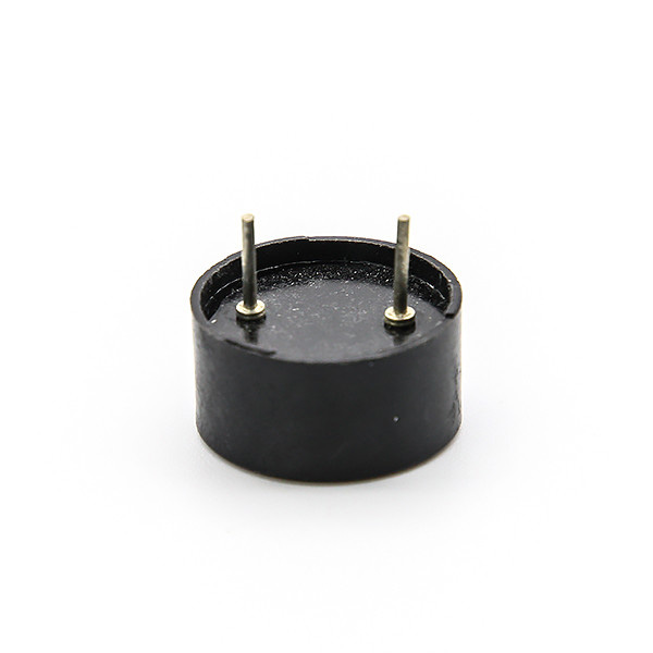
Transducer technology dictates power consumption and acoustic tone. It determines the underlying physical method used to convert electrical energy into acoustic waves. You must choose between piezoelectric and magnetic operating principles based entirely on your available power budget.
Piezoelectric transducers rely on the unique piezoelectric effect. Inside the casing, a thin piezoceramic element bonds to a metal plate. This ceramic disk physically deforms when you apply a voltage across it. When driven by an alternating signal, this rapid deformation creates acoustic waves. They boast a very high operating voltage range, often scaling up to 30V or more. Most importantly, they consume extremely little current. You will typically see current draws well below 10mA. They usually produce higher, sharper frequency outputs. They remain ideal for battery-operated projects. Handheld squeeze-ball electronics, wearable fitness trackers, and remote IoT sensors benefit immensely here. In these applications, power conservation remains your absolute primary metric.
Magnetic transducers take a completely different approach. They use a magnetic field to drive a small metal diaphragm. The internal mechanism closely resembles a traditional electromagnetic relay or a standard loudspeaker. A coil of wire sits near a magnet. Current passing through the coil creates a fluctuating magnetic field, pulling and releasing the diaphragm. They operate effectively on very low voltages, often ranging between 1.5V and 12V. However, they demand significantly higher driving current. Expect a draw ranging anywhere from 20mA up to 100mA or beyond. Because of their physical construction, they generate lower, richer, and more resonant frequencies. They are vastly superior for low-voltage systems demanding louder, deeper tones. You must simply ensure your power supply can handle the sudden current spikes without browning out the rest of the circuit.
You need specific evaluation dimensions to filter through component datasheets effectively. Reading a datasheet correctly separates a reliable design from a failing prototype.
Designers must always match their driving frequency to the datasheet's specified resonant frequency. Every acoustic chamber has a physical resonance point. This alignment is absolutely critical for performance. You only achieve peak sound pressure levels at this exact frequency. Driving the component even slightly outside this narrow band drastically reduces output volume. If the datasheet specifies 4.0kHz, configuring your PWM to 3.5kHz will result in a weak, disappointing audio alert.
We must issue a strong warning regarding current draw versus GPIO limits. Never drive high-current components directly from standard microcontroller pins. Standard Arduino, ESP32, or STM32 GPIO pins typically cap at 20 to 40mA. Pulling excess current to drive a magnetic coil will overheat and permanently fry your MCU. Always verify pin current limits before wiring your breadboard.
Physical integration dictates your manufacturing approach and scalability. You must choose the right mounting style:
Through-Hole (THT): Best suited for manual prototyping on breadboards and heavy-duty PCBs facing constant mechanical stress or vibration.
Surface Mount (SMD): Necessary for automated pick-and-place assembly lines and sleek, low-profile consumer designs.
Wire Leads or Panel Mount: Required for off-board enclosure mounting, where the sound must project outside a thick outer casing.
Environmental compliance forms the final evaluation pillar. Always check for RoHS compliance for consumer products. Review maximum operating temperature ranges to ensure viability in extreme climates or hot engine bays. If your PCB undergoes automated flux cleaning processes, you must select washable designs. Washable units feature temporary protective seal stickers to prevent cleaning fluids from destroying the internal diaphragm.
Prototyping often reveals unexpected challenges. Proper circuit protection and careful acoustic planning prevent catastrophic failures during final deployment.
When current demands exceed MCU pin limits, you must use an external switch. You can employ an NPN transistor or an N-channel MOSFET as a reliable driver. The MCU simply toggles the transistor gate using a tiny amount of current. The transistor then allows the main power rail to handle the heavy current load required by the transducer. Always include a current-limiting base resistor when using bipolar junction transistors (BJTs) to protect the MCU pin.
Magnetic variants act as inductors. When you abruptly cut power to the coil, the collapsing magnetic field generates a massive reverse voltage spike. This phenomenon is called inductive kickback. You must place a flyback diode in parallel across the component. This diode provides a safe, localized loop for the reverse current to dissipate. Without a flyback diode, this high-voltage spike will travel backward and instantly destroy your logic-level pins.
Physical implementation strongly affects perceived volume. The small hole in the component casing acts as a Helmholtz resonator. It interacts dynamically with your final product enclosure. Flush-mounting the component directly against a solid plastic wall will completely muffle the sound. You must leave adequate air gaps and align the emission hole with acoustic vents in your product casing to allow proper sound wave propagation.
If you experience low volume or distorted sound during early-stage prototyping, apply basic diagnostic logic. First, verify your driving PWM frequency perfectly matches the hardware's resonant peak. Next, measure the actual current flowing through the circuit using a multimeter. Insufficient driving current frequently causes weak audio output. Finally, check your switching transistor for thermal overload, ensuring it fully saturates when turned on.
Choose between active and passive control architectures based purely on your MCU's available processing overhead and hardware timer capabilities.
Select piezoelectric or magnetic transducers by rigorously evaluating your strict current limits versus your available operating voltage.
Prototype your exact audio profiles using basic passive components on a breadboard to validate perceived loudness before finalizing a rigid PCB layout.
Review manufacturer datasheets meticulously, focusing specifically on SPL versus distance graphs and precise resonant frequency peaks.
Finalize your hardware BOM only after simulating inductive kickback protections and verifying you remain safely below all GPIO current limits.
A: You can often identify them through simple visual cues. Active units typically feature black epoxy potting sealing the bottom, which protects the internal oscillator circuit. Passive units usually leave the green PCB exposed. Alternatively, apply a basic DC voltage test using a multimeter; an active unit will emit a steady, continuous tone, while a passive unit will only click once.
A: Generally, no. Magnetic transducers require significantly higher driving currents, typically ranging between 20mA and 100mA. Standard microcontroller GPIO pins usually max out around 20mA. Driving them directly risks permanently burning out the logic pin. You should always use an NPN transistor or MOSFET switch to handle the heavier current load safely.
A: Low volume usually stems from a frequency mismatch or severe power starvation. Check if your driving PWM frequency matches the hardware's exact resonant frequency listed in the datasheet. Operating outside this peak drastically cuts volume. Additionally, verify your driving circuit provides sufficient current and voltage to reach the target decibel level.
A: Piezoelectric models represent the gold standard for battery-powered applications. They rely on high voltage rather than heavy current to physically deform the piezoceramic element. Because they typically consume less than 10mA, they preserve precious battery life. This makes them ideal for wearables, remote sensors, and handheld devices operating on limited coin cells.


