
English 
Dedicated to global electroacoustic technology.
Views: 0 Author: Site Editor Publish Time: 2026-08-31 Origin: Site


Battery-powered devices require components drawing minimal current to maximize operating lifespan. This strict constraint makes the Piezo Buzzer an attractive choice for engineers. However, its high-impedance nature traditionally demands higher driving voltages to achieve adequate sound pressure levels (SPL).
Modern hardware designs constantly shift toward 1.5V, 3V, and 3.7V lithium-ion power architectures. We see this trend heavily in IoT sensors, medical wearables, and compact consumer electronics. These low-voltage environments directly conflict with the acoustic physics of piezoelectric materials.
Product designers and procurement engineers need a pragmatic, evidence-based framework for evaluating acoustic components. You will learn if and how a piezo transducer can meet strict audibility requirements within low-voltage constraints. We will explore circuit strategies, component evaluation, and alternative acoustic solutions.
Piezo buzzers *can* operate at low voltages (down to 1.5V or 3V), but expect a quantifiable trade-off in SPL (decibel output).
At voltages under 5V, magnetic buzzers often provide higher SPL, but draw significantly more current, threatening battery longevity.
Successful low-voltage piezo implementation relies on matching resonant frequency precisely and often requires localized boost circuitry or proper capacitor integration to prevent voltage drops.
Supply chain stability matters: with recent industry shifts (e.g., Murata EOL announcements), evaluating drop-in replacements with low-voltage capabilities is critical for continuous production.
Engineers must first define clear success criteria before selecting acoustic components. You might need to achieve a sound pressure level above 75dB at a 10cm distance. You might only have a standard 3V CR2032 coin cell available. Doing this without triggering a system reset presents a significant engineering hurdle. You must balance loudness requirements against severe power limitations.
To solve this, we must understand the physics governing acoustic output. Piezo element displacement is strictly proportional to the applied driving voltage. If you halve the driving voltage, the acoustic output drops significantly. Lower voltages mean less mechanical bending occurs across the ceramic disc. Less bending moves less air. Moving less air ultimately produces a much quieter sound. You cannot bypass this fundamental physical limitation. Expect a quantifiable trade-off when dropping from a traditional 12V rail to a 3V battery supply.
Why do engineers tolerate this lower volume? Power consumption drives the decision entirely. A typical Piezo Buzzer draws under 10mA. In many low-power applications, they draw under 5mA. Conversely, magnetic alternatives often draw between 30mA and 100mA. High current drains small batteries prematurely. It shortens the operational lifespan of IoT devices drastically. When battery life acts as the ultimate constraint, minimizing current draw becomes non-negotiable.
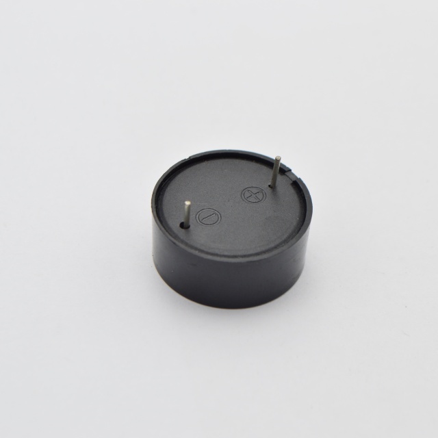
We need to contrast the two primary acoustic technologies specifically through a low-voltage lens. Choosing between them dictates your entire power management strategy. Each technology carries distinct advantages and distinct liabilities under 5V.
Acoustic Technology Comparison at Low Voltage
Feature / Specification | Magnetic Buzzers | Piezo Buzzers |
|---|---|---|
Optimal Voltage Range | 1.5V – 5V | 3V – 12V+ |
Current Consumption | High (30mA – 100mA) | Ultra-Low (<10mA) |
SPL at 3V | Generally Higher (>85dB) | Generally Lower (~70-80dB) |
EMI Generation | Yes (Inductive Coil) | No |
Physical Profile | Taller / Bulky | Flat / Low-profile |
Magnetic buzzers rely on an inductive coil to generate sound. They excel specifically in the 1.5V to 5V range.
Pros: They provide excellent low-voltage performance. They produce higher SPL at low drive voltages compared to piezo variants. They work exceptionally well on single AA or AAA batteries.
Cons: High current consumption remains their biggest flaw. Their inductive kickback requires flyback diodes to protect driving circuits. High burst currents create a severe risk of battery voltage droop.
Piezoelectric elements use a ceramic disc bonded to a metal plate. Voltage application causes the ceramic to deform rapidly.
Pros: They consume ultra-low power. They generate absolutely zero electromagnetic interference (EMI). They offer highly flat profiles. Many designs utilize low-power steel sheet piezo discs to save space.
Cons: You will get lower volume at 3V. Achieving lower resonant frequencies requires larger diameter discs. This takes up more PCB footprint.
We recommend a simple evaluation metric. If extending battery life is your primary success metric, optimize the circuit for a piezo transducer. Accept the lower volume. If your application demands immediate, loud alerting at 1.5V, magnetic components form the baseline. Ensure your battery capacity allows for the higher current surges.
How do you bridge the gap between low battery voltage and high acoustic needs? Engineers employ several specific circuit design techniques. These methods maximize the mechanical output of the Piezo Buzzer without relying on large power sources.
Sometimes a 3V battery simply cannot produce enough volume passively. You must step up the voltage. Using simple charge pump ICs or inductor-based boost converters solves this. These circuits step up a 3V battery supply to 9V or 12V specifically for the buzzer. The boost circuit remains inactive during normal operation. It only activates during an acoustic burst. This preserves battery life while delivering maximum SPL when needed.
BTL driving offers a clever workaround. You drive the buzzer across two out-of-phase microcontroller pins. When one pin pulses high, the other pulses low. This effectively doubles the peak-to-peak voltage seen by the component. A standard 3V supply becomes a 6Vpp drive. It boosts volume substantially without requiring external boost ICs. It only requires two GPIO pins instead of one.
Buzzer activation often causes a severe voltage drop. The sudden current demand dips the battery voltage. This sudden dip resets sensitive microcontrollers. Addressing this common engineering hurdle is vital. You must add parallel decoupling capacitors. Place them close to the driving circuit. A suitably sized capacitor stabilizes the power rail during acoustic bursts. It supplies the immediate current demand locally. This prevents the main battery rail from dropping below the microcontroller's brownout threshold.
Selecting the exact component dictates final system performance. You cannot simply drop any transducer onto a PCB and expect optimal results. You must evaluate several key dimensions.
At low voltages, operating strictly at the buzzer's resonant frequency is mandatory. For instance, if the datasheet specifies 4kHz, you must drive it at exactly 4kHz. It maximizes acoustic efficiency. Drifting even slightly off this frequency causes SPL to drop drastically. The mechanical disc relies entirely on resonance to amplify its minimal bending.
Evaluate self-drive (feedback) piezo components versus externally driven models. A three-pole disc includes a small feedback electrode. It simplifies the oscillating circuit by providing a built-in feedback loop. This ensures the buzzer always drives at its optimal resonant frequency. It accounts for temperature changes and aging automatically. Consider your microcontroller availability and PCB space when choosing. If you lack PWM timers, three-pole discs simplify your design.
The physical enclosure design matters immensely. At low voltages, the physical enclosure does the heavy lifting for sound amplification. A well-designed Helmholtz resonator cavity amplifies the weak mechanical output. The sound hole diameter and cavity volume must tune exactly to the driving frequency. A poorly designed cavity traps sound. A perfectly tuned cavity projects it efficiently.
Current market gaps present a real risk. Legacy manufacturers routinely issue End-of-Life (EOL) notices for staple piezo components. The Murata EOL announcements disrupted many supply chains recently. You must identify reliable alternative suppliers early. Ensure any drop-in replacement maintains identical low-voltage performance. Requesting physical samples for acoustic testing is mandatory before approving a substitute.
Transitioning from a prototype to a mass-produced device introduces specific reliability factors. Testing purely under ideal laboratory conditions guarantees field failures.
Consider actual battery discharge curves carefully. A standard 3V lithium coin cell drops to 2.5V near its end of life. The buzzer must still meet minimum audibility compliance at 2.5V. If you only test at a fresh 3.2V, your product will fail prematurely in the field.
Another risk involves micro-signal triggering. Microcontroller logic pins often supply very low current. You must use SCRs or NPN transistors. They reliably switch the buzzer using low-current MCU logic pins. Do not drive the component directly from a weak GPIO pin.
Follow a structured path when narrowing down your options.
Define the minimum acceptable SPL and your specific target distance.
Determine the maximum allowable peak current your battery can handle safely.
Select the buzzer type based on limits. Use Piezo for low current. Use Magnetic for high SPL at low voltages.
Design a targeted acoustic cavity and optimize the driving circuit simultaneously.
Do not rely solely on nominal 12V specifications printed on the front page of a datasheet. Request physical engineering samples. Review datasheet frequency response curves at your actual battery voltages. Consult component application engineers directly. They provide invaluable insight into custom tuning and cavity design. Rigorous testing prevents costly redesigns later.
Piezo transducers are highly viable for low-voltage battery devices. Engineering teams must accept the SPL trade-offs willingly. Success demands optimizing both the driving circuit and the acoustic enclosure. Relying on passive driving limits performance significantly.
There is no magic component available on the market. Superior acoustic performance relies entirely on careful matching. You must balance acoustic impedance, driving voltage, and strict current limitations. Proper testing validates these theoretical matches.
Download a low-voltage buzzer selection guide today. Cross-reference any EOL parts quickly to protect your supply chain. Contact technical sales to request custom acoustic profiling for your specific device enclosure.
A: Yes, but it will be significantly quieter. A buzzer rated for 12V driven at 3V may see an SPL reduction of 15dB or more. It is always better to specify a component explicitly optimized for 3V operation. This ensures you maximize acoustic output given the restricted power.
A: Sudden current demands cause battery voltage droop. When the voltage dips below the microcontroller's operating threshold, it resets. We recommend adding a suitably sized capacitor across the power rails near the buzzer. This decoupling capacitor supplies the burst current locally, protecting the main power rail.
A: Generally, yes. Magnetic buzzers operate efficiently at 1.5V. They provide louder outputs than piezo alternatives at this voltage. However, the battery source, like an AAA or AA cell, must handle the 30mA or higher current draw required comfortably.
A: A 3-pole feedback disc simplifies the oscillating circuit by providing a built-in feedback loop. This ensures the buzzer always drives at its optimal resonant frequency. Striking this exact frequency is critical for maximizing volume when your driving voltage is heavily restricted.


